Input apparatus and control method for input apparatus

Active Publication Date: 2012-06-21
KYOCERA CORP
View PDF3 Cites 36 Cited by
  • Summary
  • Abstract
  • Description
  • Claims
  • Application Information

AI Technical Summary

Benefits of technology

[0036]The input apparatus according to the present invention, utilizing direct piezoelectric effect and converse piezoelectric effect of the piezoelectric element, uses the piezoelectric element as a load sensor to detect the pressure load on the touch face of the touch sensor and as an actuator to vibrate the touch face. It is thus possible to reduce the number of components and the cost as well as to save space for the components for downsizing the apparatus. In addition, after drive of the piez

Problems solved by technology

Since the touch sensors are not physically displaced when touched, an operator cannot obtain feedback to an input even when the touch input is received.
As a result, the operator is likely to input erroneously by touching the same spot multiple times, which may be stressful for the operator.
However, such auditory feedback may be difficult to be confirmed in a noisy env

Method used


Image

  • Input apparatus and control method for input apparatus
  • Input apparatus and control method for input apparatus
  • Input apparatus and control method for input apparatus

Examples


Example

First Embodiment

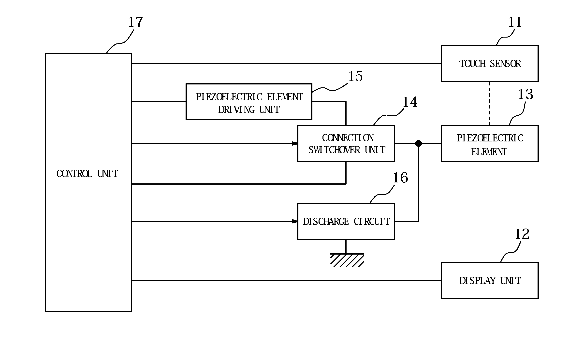
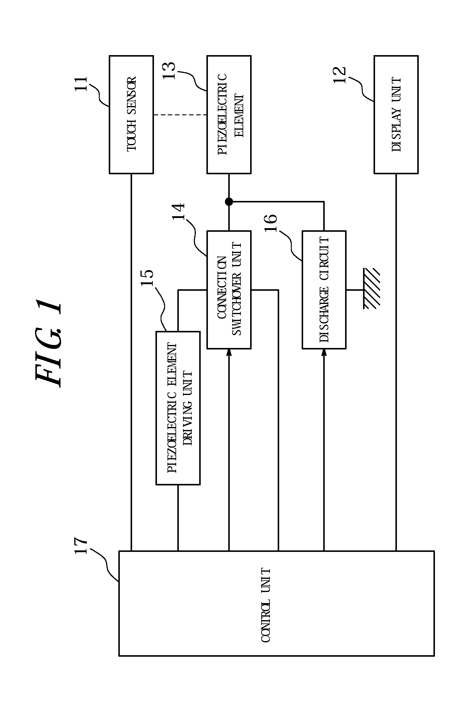
[0044]FIG. 1 is a functional block diagram illustrating a schematic configuration of an input apparatus according to a first embodiment of the present invention. This input apparatus has a touch sensor 11, a display unit 12, a piezoelectric element 13, a connection switchover unit 14, a piezoelectric element drive unit 15, a discharge circuit 16, and a control unit 17 to control an operation of each unit.

[0045]The touch sensor 11 is connected to the control unit 17 and, under control of the control unit 17, detects a touch input to a touch face of the touch sensor 11 by a pressing object, such as a finger and the like, and provides the control unit 17 with position information of a touch position. The touch sensor 11 may be of a known type, such as a resistive film type, a capacitive type, an optical type and the like, and disposed on the display unit 12.

[0046]The display unit 12 is connected to the control unit 17 and, under control of the control unit 17, displays ...

Example

Second Embodiment

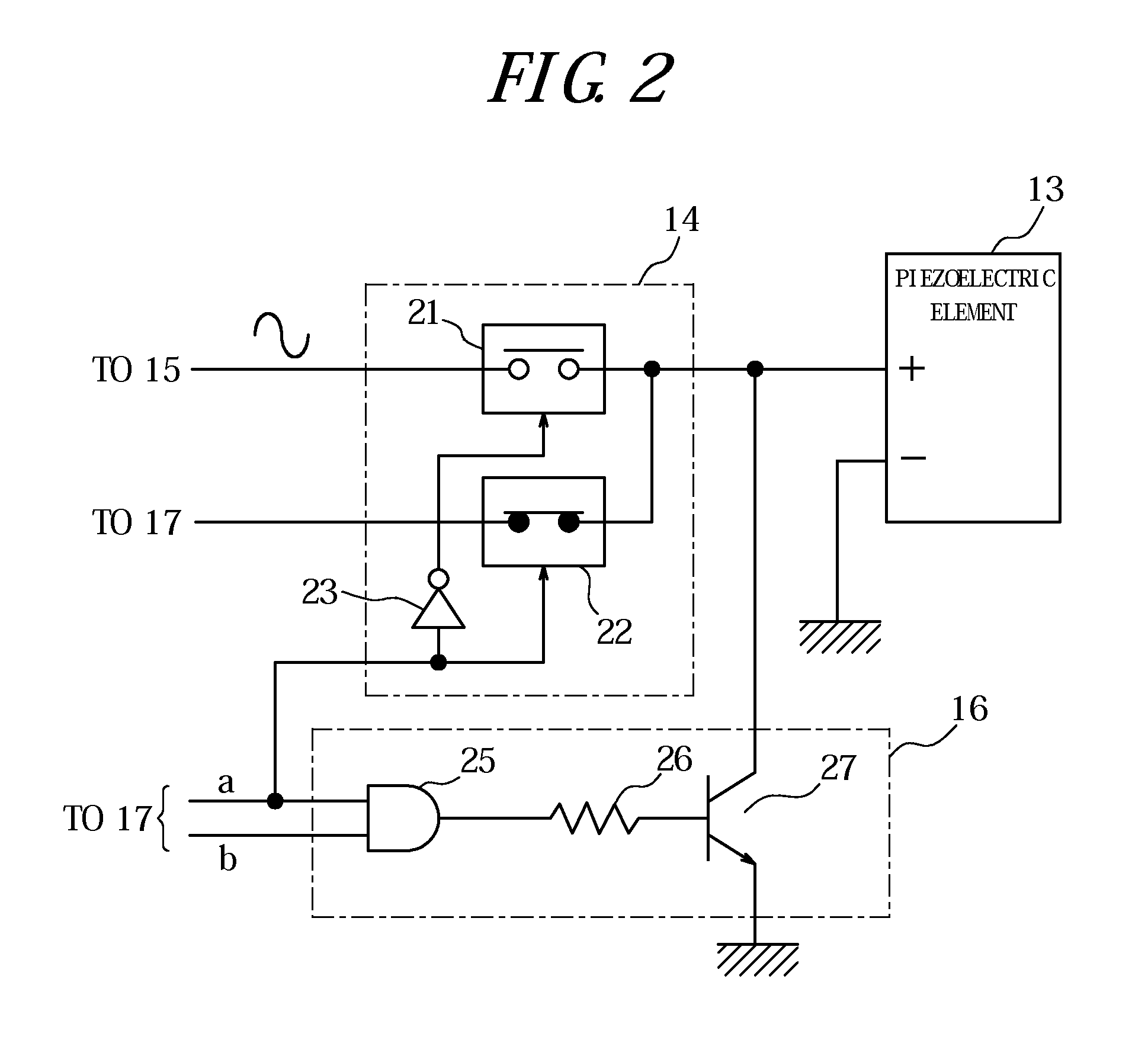
[0064]FIG. 4 is a circuit configuration diagram of a main section of an input apparatus according to a second embodiment of the present invention. This input apparatus has the same configuration as that in FIG. 2, except for configuring a discharge circuit 16 by a resistor element 28 connected between the positive electrode terminal of the piezoelectric element 13 and ground in the circuit diagram illustrated FIG. 2. Therefore, the same components as those illustrated in FIG. 2 are provided with the same reference signs and descriptions thereof are omitted.

[0065]According to the input apparatus of the present embodiment, in order to discharge the residual electric charge in the piezoelectric element 13 through the resistor element 28, the piezoelectric element 13 is connected to the piezoelectric element drive unit 15 for the period T1 illustrated in FIG. 3 when the piezoelectric element drive unit 15 drives the piezoelectric element 13. Thereby, the piezoelectric e...


PUM


Abstract

An input apparatus includes: a touch sensor 11; a piezoelectric element 13; a piezoelectric element drive unit 15; a control unit 17 configured to detect a pressure load on the touch sensor 11 based on an output signal of the piezoelectric element 13 and, when the pressure load satisfies a standard to provide a tactile sensation, to control the piezoelectric element drive unit 15 to drive the piezoelectric element 13 such that the tactile sensation is provided to a pressing object; a connection switchover unit 14 configured to selectively connect the piezoelectric element 13 to the control unit 17 or the piezoelectric element drive unit 15; and a discharge circuit 16 configured to discharge electric charge in the piezoelectric element 13. When the pressure load satisfies the standard, the control unit 17 controls the connection switchover unit 14 to connect the piezoelectric element 13 to the piezoelectric element drive unit 15 such that the piezoelectric element 13 is driven, and then controls the discharge circuit 16 to discharge the electric charge in the piezoelectric element 13.

Description

CROSS REFERENCE TO RELATED APPLICATION[0001]This application claims priority to and the benefit of Japanese Patent Application No. 2009-197377 filed on Aug. 27, 2009, the entire contents of which are incorporated herein by reference.TECHNICAL FIELD[0002]The present invention relates to an input apparatus having a touch sensor and a control method for an input apparatus.BACKGROUND ART[0003]In recent years, input apparatuses having touch sensors such as touch panels, touch switches or the like are popularly used as input apparatuses such as operation units, switches and the like for receiving input operations by a user in mobile terminals such as mobile phones, information equipments such as calculator, ticket vending machines, home electric appliances such as microwaves, TV sets, lighting equipments, industrial equipments (FA equipments) and the like.[0004]There are known a variety of types of those touch sensors, such as a resistive film type, a capacitive type, an optical type and ...

Claims


Application Information

Patent Timeline
IPC IPC(8): G06F3/041G06F3/045
CPCG06F3/016G06F3/0416G06F3/0414G06F3/04142
Inventor SHIMIZU, KATSUHIKO
Owner KYOCERA CORP
Why Eureka
Try Eureka