
Imaging apparatus and method

Inactive Publication Date: 2012-06-21
SAMSUNG ELECTRONICS CO LTD
View PDF2 Cites 3 Cited by
  • Summary
  • Abstract
  • Description
  • Claims
  • Application Information

AI Technical Summary

Benefits of technology

[0013]Accordingly, the present invention provides to an imaging apparatus capable of decreasing degradation in the AF function while also decreasing the amount of hardware resources consumed.

Problems solved by technology

That is, AF cannot be implemented.
However, the conventional technique has some problems as will be discussed below.
The technique disclosed in Japanese Patent Application Publication No. 2005-326621 requires a memory region for storing a 90° rotated image and increases the memory cost.

Method used


Image

  • Imaging apparatus and method
  • Imaging apparatus and method
  • Imaging apparatus and method

Examples


Embodiment Construction

[0029]Hereinafter, an embodiment of the present invention will be described in detail with reference to the accompanying drawings. In the following description, specific details such as the detailed configuration and components are merely provided to assist with the overall understanding of the embodiment of the present invention. Therefore, it should be apparent to those skilled in the art that various changes and modifications of the embodiment described herein can be made without departing from the scope and spirit of the invention. The detailed descriptions of functions and configurations incorporated herein that are well known to those skilled in the art will be omitted to avoid unnecessarily obscuring the present invention.

[0030]Hereinafter, an imaging apparatus according to an embodiment of the present invention will be described with reference to the accompanying drawings.

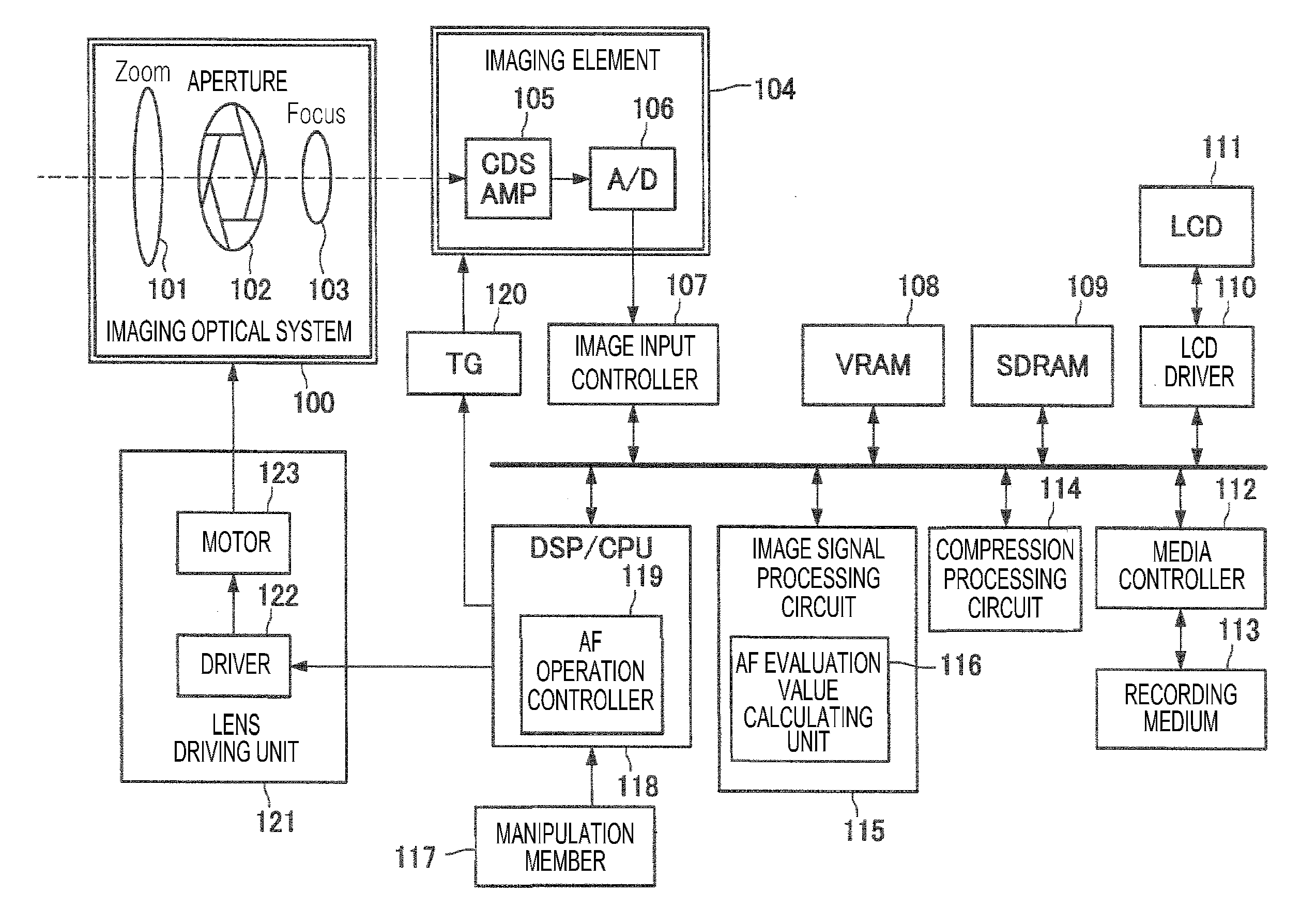
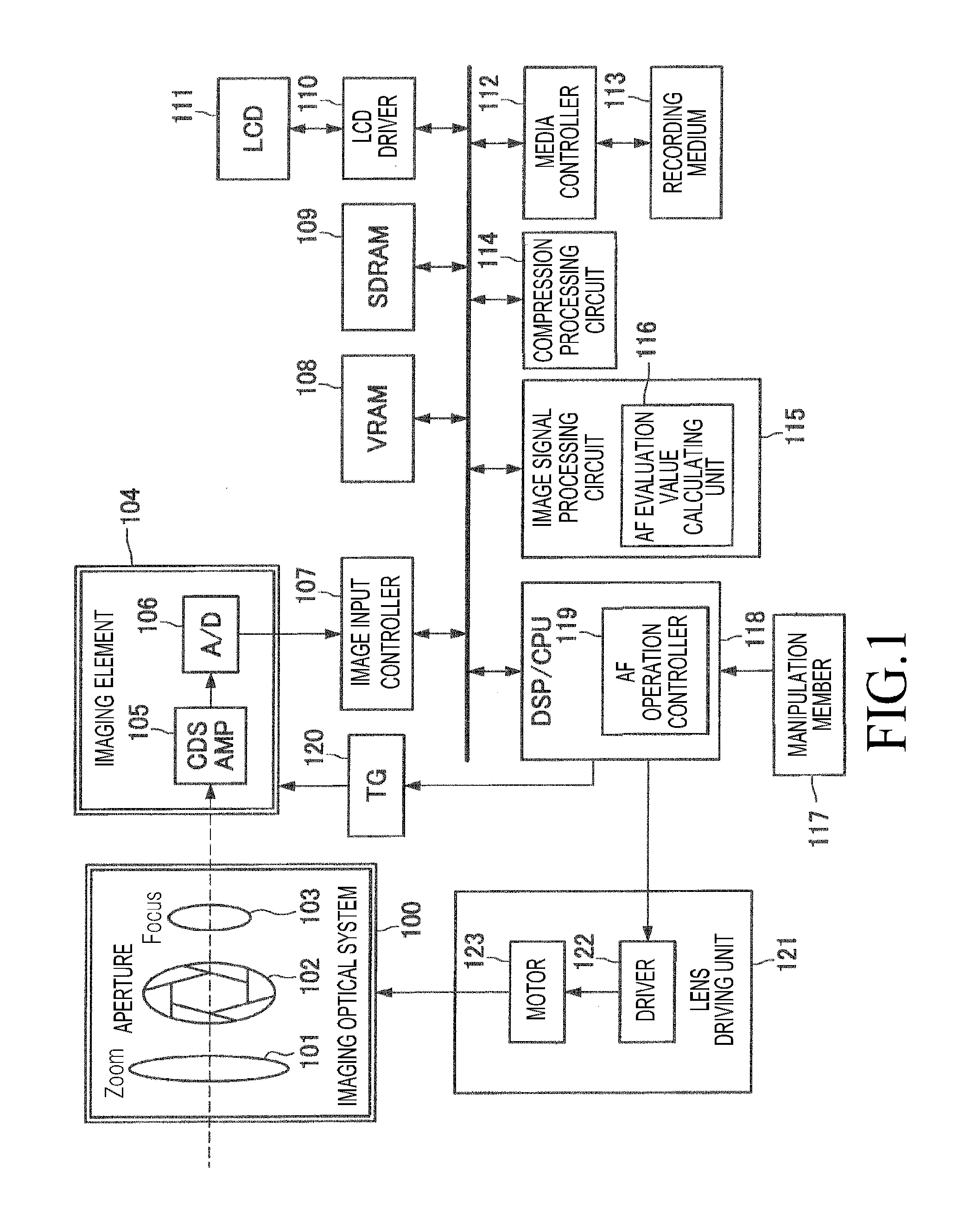
[0031]FIG. 1 is a block diagram of an imaging apparatus 1000 according to an embodiment of the present i...


PUM


Abstract

An imaging apparatus that adjusts focus based on frequency components extracted from an image signal is provided. The apparatus includes a 1st order Infinite Impulse Response (IIR)-filter including a plurality of sample delayers having a plurality of line buffers for buffering and delaying a plurality of samples to sequentially read pixels of the image signal through raster scanning and extracting frequency components of the image signal from the read pixels by using the plurality of sample delayers; and a delay sample number controller for controlling the IIR-filter to match the number of horizontal pixels sequentially read from the image signal through raster scanning to the number of the plurality of samples buffered by the plurality of line buffers, wherein the delay sample number controller commands the IIR-filter to read a sample from each of the plurality of line buffers in a direction perpendicular to a direction of the raster scanning, and perform filtering processing on the read sample.

Description

PRIORITY[0001]This application claims priority under 35 U.S.C. §119(a) to a patent application filed in the Japan Patent Office on Dec. 21, 2010 and assigned Serial No. JP 284947 / 2010, and a patent application filed in the Korean Intellectual Property Office on Nov. 18, 2011 and assigned Serial No. 10-2011-0121076, the entire disclosures of which are incorporated herein by reference.BACKGROUND OF THE INVENTION[0002]1. Field of the Invention[0003]The present invention relates generally to an imaging apparatus and an imaging method.[0004]2. Description of the Related Art[0005]Conventionally, a digital still camera, a camera-mounted cellular phone, a digital video camera, and so forth provide an Auto Focus (AF) function for automatically adjusting focus. The AF can be divided roughly into two schemes: a phase difference detection scheme for optically measuring a distance to an object by using a range-finding sensor and a contrast detection scheme for detecting a position at which a con...

Claims


Application Information

Patent Timeline
IPC IPC(8): H04N5/232
CPCH04N5/23212H04N23/673H04N23/631
Inventor WADA, NAOFUMI
Owner SAMSUNG ELECTRONICS CO LTD
Learn More