Nuclear reactor automatic depressurization system

a technology of nuclear reactors and depressurization systems, applied in nuclear engineering, nuclear elements, greenhouse gas reduction, etc., can solve the problems of blocking devices failing, blocking devices not preventing the depressurization system from activating,

Active Publication Date: 2012-06-21
WESTINGHOUSE ELECTRIC CORP
View PDF14 Cites 19 Cited by
  • Summary
  • Abstract
  • Description
  • Claims
  • Application Information

AI Technical Summary

Benefits of technology

[0013]To achieve the foregoing objectives, this invention provides a nuclear reactor system having a pressurized coolant circuit including a pressure vessel, heat exchanger, core makeup tank and connecting piping, with the connecting piping including a main coolant loop piping connecting the heat exchanger to the pressure vessel in a closed loop configuration and a makeup water connection connecting the core makeup tank to the pressure vessel. The nuclear reactor system is housed within a containment shell that also has an in-containment water reservoir that is maintained vented to an atmosphere of the containment shell. The nuclear reactor system further includes a depressurization system for automatically depressurizing the pressurized coolant circuit in the event of a design basis accident and connecting the water reservoir to the pressure vessel. A blocking device is connected to the depressurization system for preventing the depressurization system from activating when coolant within the core makeup tank is above a preselected level. Preferably, the blocking device fails in a failsafe condition wherein the failure of substantially any component within the blocking device will stop the blocking device from preventing the depressurization system from activating. Desirably, the preselected level is a level at which the core makeup tank is considered substantially full.
[0014]In one embodiment, the core makeup tank includes more than one water tank connected to the pressure vessel and wherein the blocking device prevents the depressurization system from activating when coolant in each of the water tanks is above the preselected level. Preferably, the blocking device does not prevent the depressurization system from activating when coolant within any of the water tanks is below the preselected level.

Problems solved by technology

Preferably, the blocking device fails in a failsafe condition wherein the failure of substantially any component within the blocking device will stop the blocking device from preventing the depressurization system from activating.
Preferably, the blocking device does not prevent the depressurization system from activating when coolant within any of the water tanks is below the preselected level.

Method used


Image

  • Nuclear reactor automatic depressurization system
  • Nuclear reactor automatic depressurization system
  • Nuclear reactor automatic depressurization system

Examples


Embodiment Construction

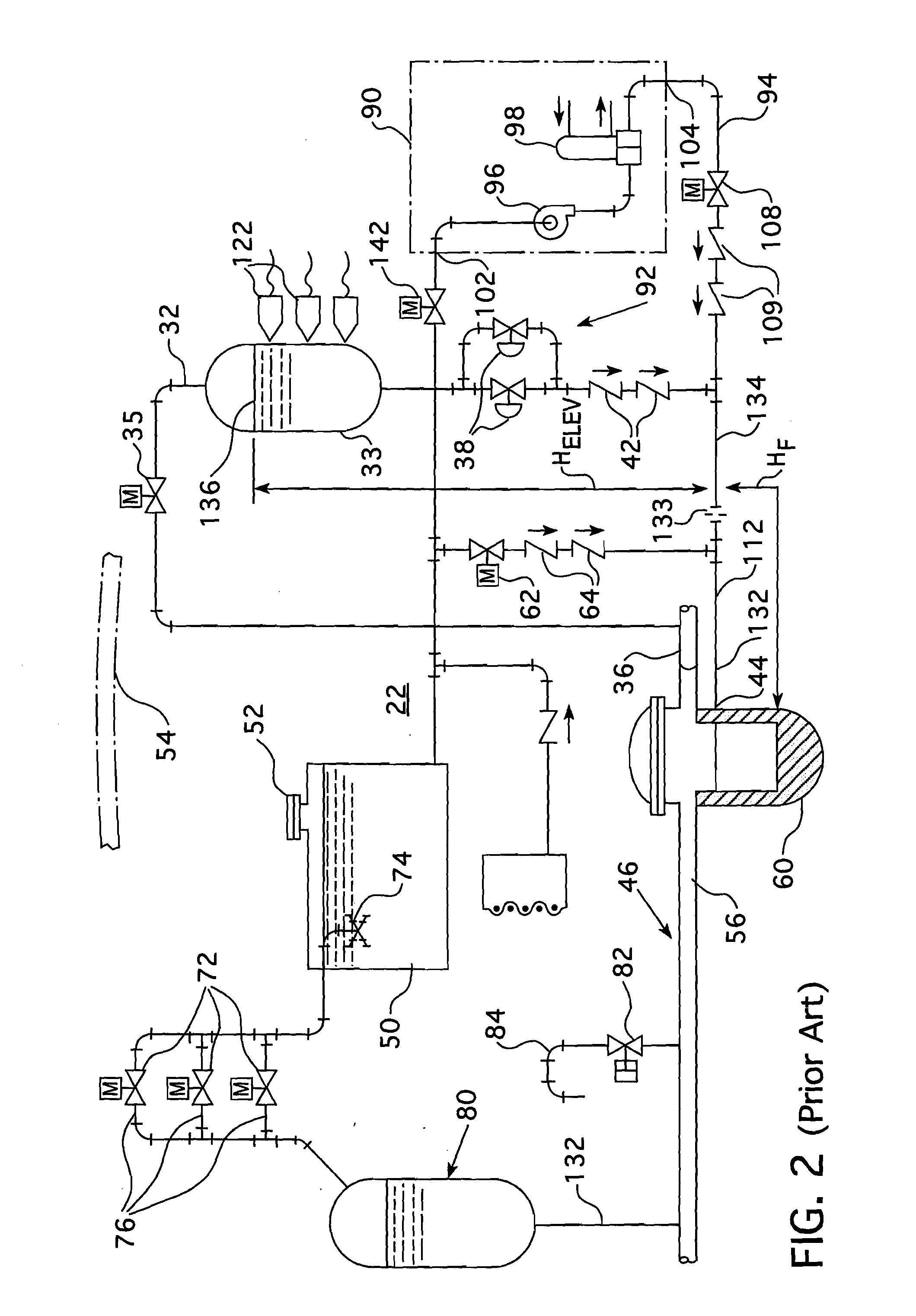
[0021]From FIG. 2, it can be appreciated that there are two sources of coolant to make up for loss of the coolant in the AP1000 nuclear reactor system 22. An inlet 32 of the high pressure core makeup tank 33 is coupled by valves 35 to the reactor coolant inlet or “cold leg”36. The high pressure core makeup tank 33 is also coupled by motorized valves 38 and check valves 42 to a reactor vessel injection inlet 44. The high pressure core makeup tank 33 is operable to supply additional coolant to the reactor coolant circuit 46, at the operational pressure of the reactor, to make up for relatively small losses. However, the high pressure core makeup tank 33 contains only a limited supply of coolant, though, as can be appreciated from FIG. 1, there are two core makeup tanks in the system.

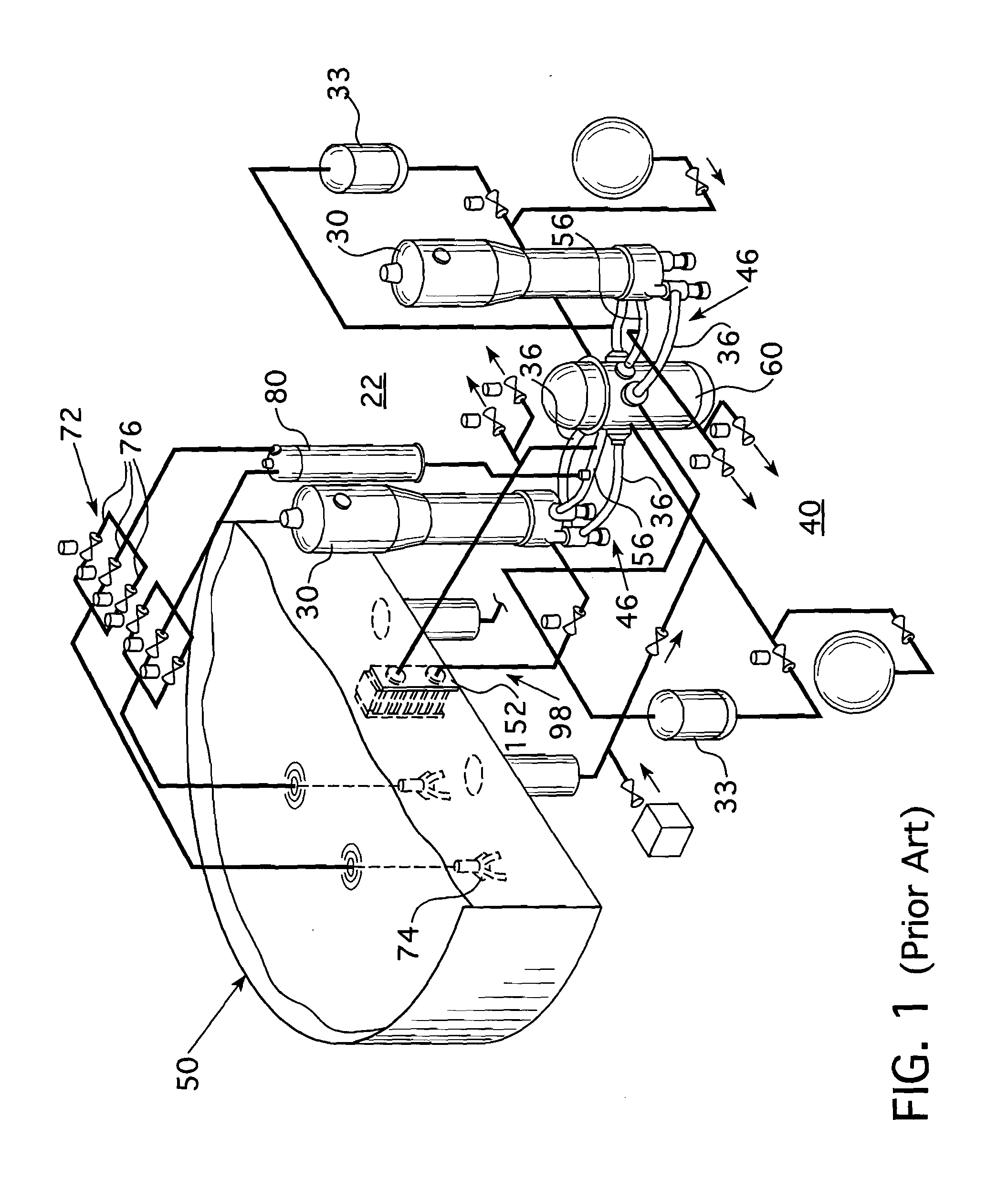
[0022]A much larger quantity of coolant water is available from the in-containment refueling water storage tank 50, at atmospheric pressure due to vent 52, which opens from the tank 50 into the interior of...


PUM


Abstract

A blocking device for preventing the actuation of an automatic depressurization system in a pressurized nuclear reactor system due to spurious signals resulting from a software failure. The blocking signal is removed when the coolant level within the core makeup tanks drop below a predetermined level.

Description

BACKGROUND OF THE INVENTION[0001]1. Field of the Invention[0002]This invention relates in general to pressurized water nuclear reactors and, in particular, to systems for injecting additional coolant into the reactor coolant circuit in the event of a postulated accident. The invention is applicable to reactor systems having passive safety features with automatic depressurization of the reactor coolant circuit to facilitate the injection of additional coolant water.[0003]2. Related Art[0004]A nuclear reactor, such as a pressurized water reactor, circulates coolant at high pressure through a coolant circuit traversing a reactor pressure vessel containing nuclear fuel for heating the coolant and a steam generator operable to extract energy from the coolant for useful work. A residual heat removal system is typically provided to remove decay heat from the pressure vessel during shutdown. In the event of a loss of coolant, means are provided for adding additional coolant. A coolant loss ...

Claims


Application Information

Patent Timeline
Patent Type & Authority Applications(United States)
IPC IPC(8): G21C9/004
CPCG21C9/004Y02E30/40G21D3/06G21C15/18H03K19/007Y02E30/30
Inventor COOK, BRUCE M.
Owner WESTINGHOUSE ELECTRIC CORP
Why Eureka
Try Eureka