Screw structure

a screw and structure technology, applied in the direction of screws, threaded fasteners, fastening means, etc., can solve the problems of increasing the difficulty of screwing forward, increasing the friction force, and the tip would encounter the resistance of the material, so as to improve the drilling effect of screws, less effort, and faster and firmer fastening

Inactive Publication Date: 2012-06-21
CHAO CHIEN CHIN
View PDF5 Cites 4 Cited by
  • Summary
  • Abstract
  • Description
  • Claims
  • Application Information

AI Technical Summary

Benefits of technology

[0004]The primary object of the present invention is to overcome the aforesaid disadvantages of the conventional screws by providing an improved screw with a novel shank and right-hand and left-hand thread sections to enhance screw drilling effect based on mechanics to achieve faster and firmer fastening with less effort.
[0006]By means of the structure set forth above, the invention provides many benefits, notably:
[0007]1. With the triangular shank at the lower end and the round shank at the upper end of the screw, when the triangular shank is screwed into a workpiece, the contact area with the workpiece is reduced, and resistance encountered during tapping is smaller, thus construction can be done faster with less effort.
[0009]3. With the saw-toothed threads formed on the lower thread section of the triangular shank, fibers of the workpiece can be damaged faster during screwing to improve construction efficiency.

Problems solved by technology

However, when the screw is screwed into the workpiece, the tip would encounter resistance of the material during cutting and squeezing.
Since the shank of the screw is usually formed in a round section and the threads are in contact with the workpiece in line or surface during screwing, greater friction force is generated and difficulty of screwing forward is increased.
Users have to exert more efforts and time to fasten the screw to the workpiece, and construction efficiency suffers.

Method used


Image

  • Screw structure
  • Screw structure
  • Screw structure

Examples


Embodiment Construction

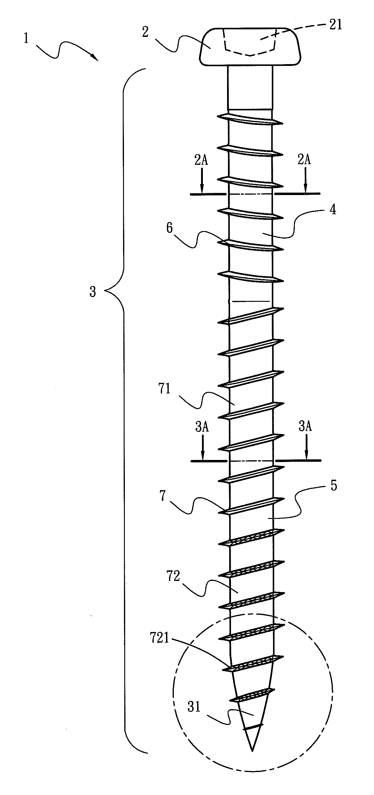
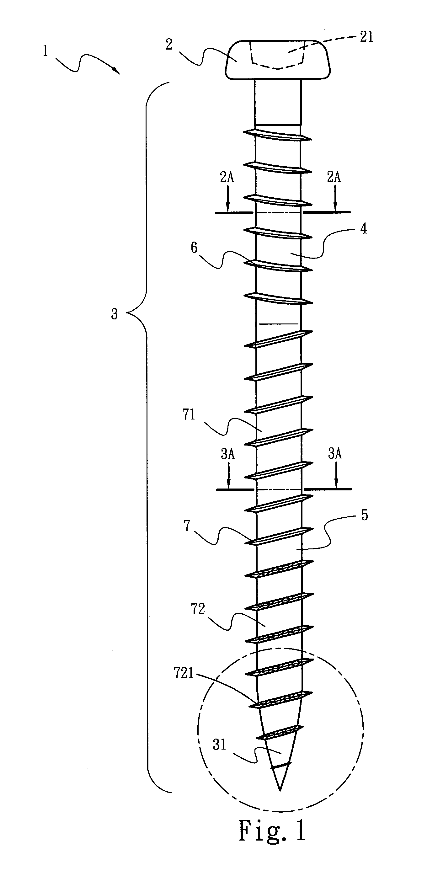
[0015]Please refer to FIGS. 1 through 4, the present invention provides an improved screw 1 which includes a head 2 and a shank 3 connected to the bottom of the head 2.

[0016]The head 2 has a wrench cavity 21 on the top to be driven by a screwdriver.

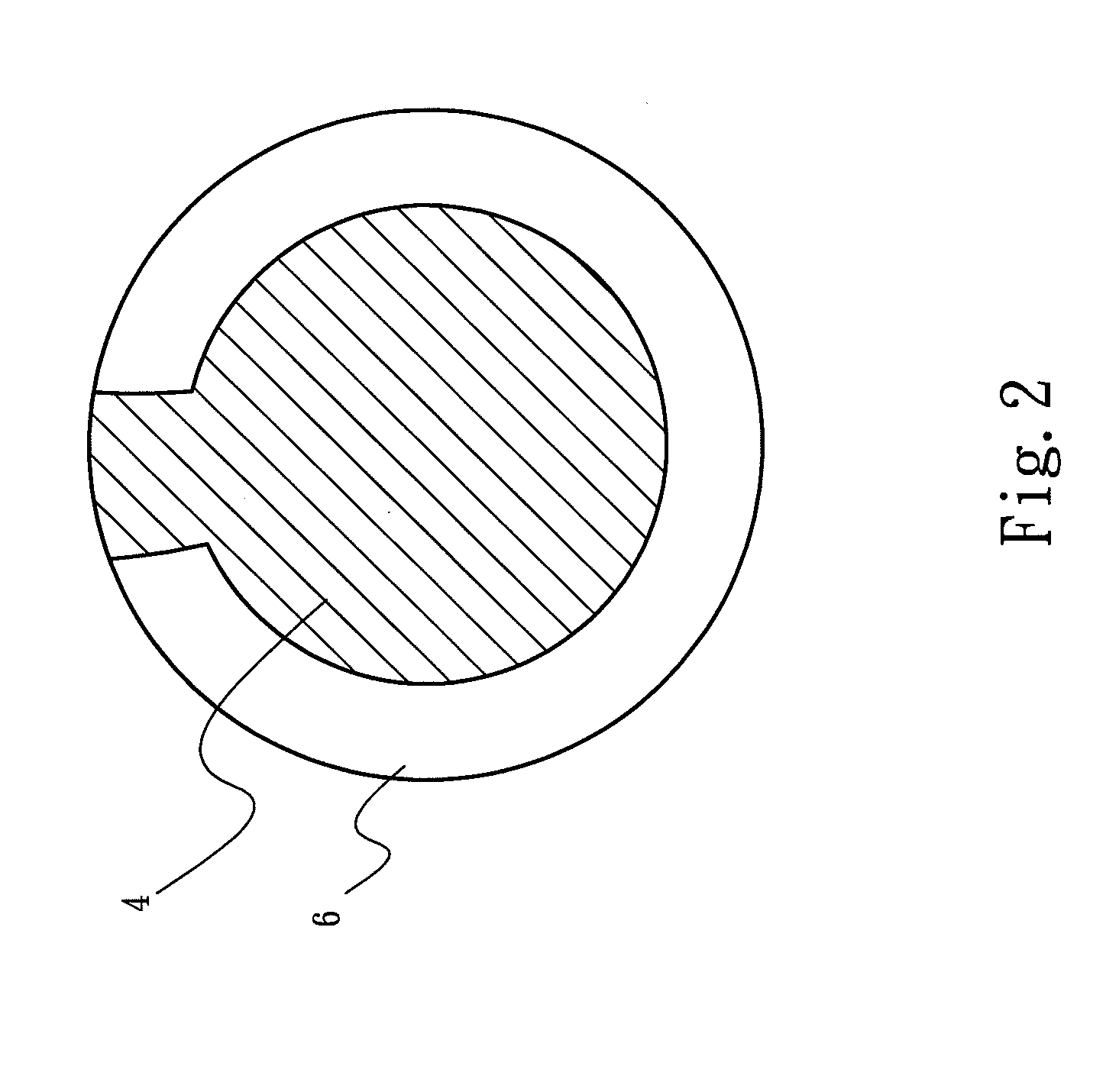
[0017]The shank 3 has a tip 31 at the bottom end and a round shank 4 at an upper end close to the head 2 and a triangular shank 5 for the remained portion of the shank 3 at a lower end. The round shank 4 has a left-hand thread section 6 formed annularly thereon in a circular profile (referring to FIG. 2). The triangular shank 5 has a right-hand thread section 7 formed annularly thereon in a triangular profile (referring to FIG. 3). The left-hand and right-hand thread sections 6 and 7 have thread points formed in an asymmetrical manner with unequal inclined angles. However, this is a technique known in the art, thus details are omitted herein. The right-hand thread section 7 further has an upper thread section 71 and a lower thread section...


PUM

PropertyMeasurementUnit
lengthaaaaaaaaaa
resistanceaaaaaaaaaa
friction forceaaaaaaaaaa

Abstract

An improved screw includes a head and a shank. The head has a wrench cavity on the top to be driven by a screwdriver. The shank is connected to the bottom of the head. The shank has a round shank at an upper end close to the head to form a left-hand thread section, and a triangular shank at a lower end to form a right-hand thread section. The left-hand and right-hand thread sections have thread points formed in an asymmetrical manner. The right-hand thread section further has an upper thread section and a lower thread section at the bottom to form the tip. The lower thread section has saw-toothed threads. Thus tapping efficiency improves when the screw is fastened to a workpiece, and faster and firmer fastening can be achieved.

Description

FIELD OF THE INVENTION[0001]The present invention relates to a screw structure and particularly to an improved screw that has a triangular shank with right-hand threads and a round shank with left-hand threads to enhance construction efficiency and achieve firmer fastening.BACKGROUND OF THE INVENTION[0002]Screws are widely used for coupling non-metal workpieces such as plastics and woods. A screw generally has a tip at the front end to pierce a workpiece, then is screwed forwards through threads which cut and squeeze the material of the workpiece to form corresponding threads to attain secure fastening.[0003]However, when the screw is screwed into the workpiece, the tip would encounter resistance of the material during cutting and squeezing. Since the shank of the screw is usually formed in a round section and the threads are in contact with the workpiece in line or surface during screwing, greater friction force is generated and difficulty of screwing forward is increased. Users ha...

Claims


Application Information

Patent Timeline
Patent Type & Authority Applications(United States)
IPC IPC(8): F16B35/04
CPCF16B25/0015F16B25/0052F16B25/106F16B25/0073F16B25/0078F16B25/0057
Inventor CHAO, CHIEN-CHIN
Owner CHAO CHIEN CHIN
Why Eureka
Try Eureka