Axial ultrasonic vibration drilling device fixed by lathe carriage

A technology of lathe tool holder and ultrasonic vibration, which is applied in the direction of boring/drilling device, fluid using vibration, boring machine/drilling machine parts, etc., which can solve the problems of inconvenient disassembly and assembly of the device, high cost and complicated structure, and achieve convenient installation, The effect of reducing drilling force and simplifying the structure

Inactive Publication Date: 2017-02-22
NORTHEASTERN UNIV
View PDF6 Cites 7 Cited by
  • Summary
  • Abstract
  • Description
  • Claims
  • Application Information

AI Technical Summary

Problems solved by technology

[0005] However, most of the current research is carried out on the drilling machine. Since the drill bit and the ultrasonic vibration device rotate with the spindle of the drilling machine, in order to avoid the winding phenomenon of the ultrasonic vibration device during rotation, a collector ring or carbon brush is required to convert the energy in the ultrasonic vibration device. The power supply of the device, and the drilling machine needs to be greatly modified, so the structure is complex, resulting in inconvenient disassembly and assembly of the device, and the cost is high

Method used


Image

  • Axial ultrasonic vibration drilling device fixed by lathe carriage
  • Axial ultrasonic vibration drilling device fixed by lathe carriage
  • Axial ultrasonic vibration drilling device fixed by lathe carriage

Examples


Embodiment Construction

[0023] The present invention will be further described in detail below in conjunction with the accompanying drawings and specific embodiments.

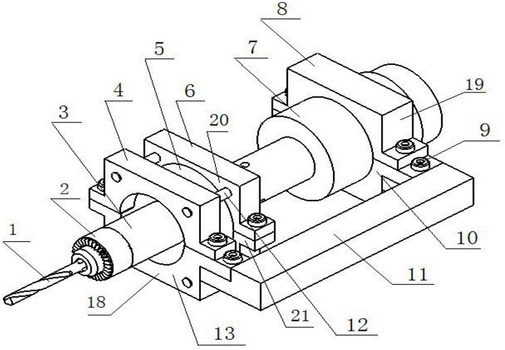
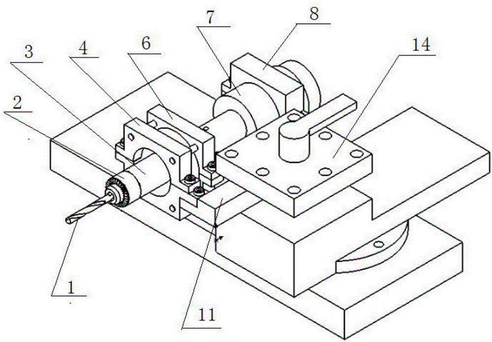
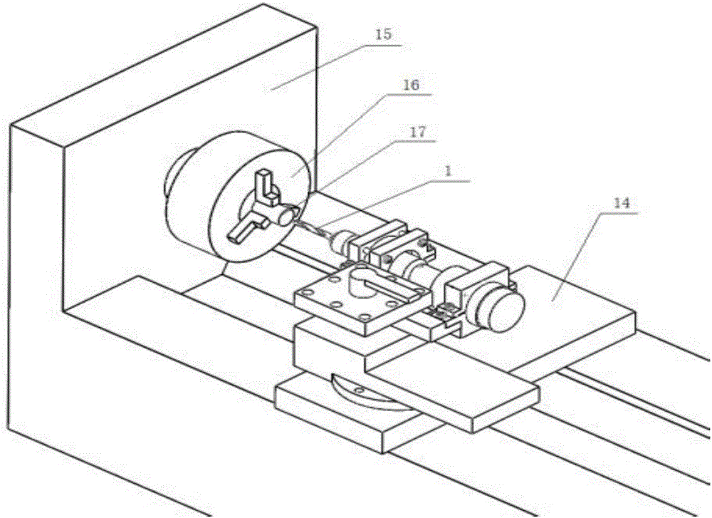
[0024] Such as Figure 1 to Figure 3 The shown a kind of axial ultrasonic vibration drilling device that is fixed by lathe turret comprises ultrasonic vibration device and cantilever type fixing device, and described ultrasonic vibration device comprises a drill bit 1, horn 3, transducer 7 and The transducer 7 is connected to an ultrasonic generator (not shown) by wires.

[0025] Such as figure 1 and Figure 4 As shown, the drill bit 1 is fixed on the drill chuck 2, the drill chuck 2 is connected to the front end of the horn 3 through a first stud, and the drill bit 1 and the horn 3 Keeping the coaxial arrangement, the transducer 7 is connected to the rear end of the horn 3 through a second stud. Such as figure 1 , figure 2 and image 3 As shown, the cantilever beam type fixing device is fixed on the lathe tool rest 14, includ...


PUM

PropertyMeasurementUnit
diameteraaaaaaaaaa

Abstract

Provided is an axial ultrasonic vibration drilling device fixed by a lathe carriage. The axial ultrasonic vibration drilling device fixed by the lathe carriage comprises a drill, an amplitude-change pole, a transducer, a beam hanging type fixed device and an ultrasonic generator electrically connected to the transducer. The beam hanging type fixed device comprises a hanging beam fixed on the lathe carriage and a front pressing plate and a rear pressing plate, wherein the front pressing plate and the rear pressing plate are fixedly connected to the hanging beam, the front pressing plate fixes the front end of the amplitude-change pole, the rear pressing plate fixes the transducer, a fixed pressing plate fixes the middle part of the amplitude-change pole, and the front pressing plate, the rear pressing plate and the fixed pressing plate are all divided into upper and lower two parts and are assembled through bolts. Compared with a drilling device achieved on a drilling machine, there is no need to conduct any special refit on a machine tool; in addition, a method of workpiece revolution is adopted, there is no need to use assembly units such as a ring manifold or a carbon brush, thus the structure is simplified, the cost is saved, and the axial ultrasonic vibration drilling device fixed by the lathe carriage is convenient to disassemble and assemble and is beneficial to a proceeding of ultrasonic vibration drilling.

Description

[0001] Technical field: [0002] The invention belongs to the technical field of machining, and in particular relates to an axial ultrasonic vibration drilling device. [0003] Background technique: [0004] In the field of mechanical manufacturing, various difficult-to-machine materials are increasingly widely used, and the number of micro-holes increases, which makes the processing of holes more and more difficult. In addition, the shape of workpieces is becoming more and more complex, which affects surface roughness, precision and certain The standards that need to be met for special requirements are getting higher and higher, which puts forward higher requirements for machining technology. Due to the problems of high drilling force, high drilling temperature and difficult chip removal in the traditional drilling process, it is easy to cause severe drill wear and low drill life, which reduces the drilling efficiency and increases the processing cost. Therefore, traditional ...

Claims


Application Information

Patent Timeline
Patent Type & Authority Applications(China)
IPC IPC(8): B23B43/00B23B47/00B06B1/02
CPCB23B43/00B06B1/02B23B47/00
Inventor 邹平田英健陈硕康迪
Owner NORTHEASTERN UNIV
Why Eureka
Try Eureka