Full helicoidal surface Micro-drill web thinning method

A drill chisel edge, chisel edge grinding technology, used in twist drills, drill accessories, drilling/drilling equipment, etc. The small size of the micro-drill has the effect of improving the drilling performance, the drilling performance and the centering ability.

Inactive Publication Date: 2007-12-05
HUNAN UNIV
View PDF0 Cites 9 Cited by
  • Summary
  • Abstract
  • Description
  • Claims
  • Application Information

AI Technical Summary

Problems solved by technology

However, due to the small size of the micro-drill itself, it is impossible to use the method of grinding the chisel edge of ordinary twist drills and group drills to solve the problem of grinding the chisel edge, and a new method of grinding the chisel edge must be studied
[0003] Full helical drill point flank F 1 and F 2 After sharpening, the chisel edge of the drill tip has a sharp angle of 180° at the drill core tip, which is not conducive to the drilling of the drill bit, and the drill bit is prone to slippage on the surface of the workpiece
In addition, the chisel edge has a large negative rake angle, so there will be strong extrusion with the workpiece during the cutting process
In other words, the centering performance and cutting performance of the chisel edge are not good

Method used


Image

  • Full helicoidal surface Micro-drill  web thinning method

Examples


Embodiment 1

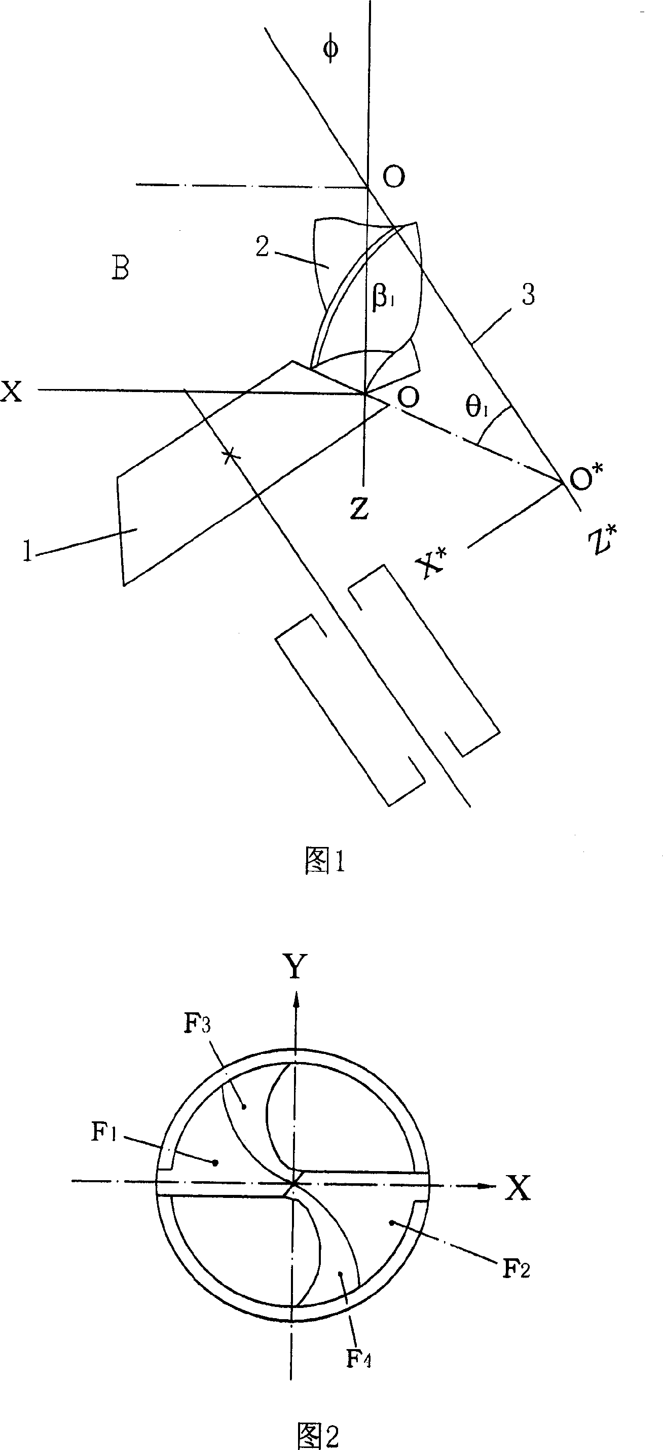
[0012] Embodiment 1: The drill bit 2 is fixed, and the grinding wheel moves. According to the parameters in Figure 1, adjust the relative position of the grinding wheel 1 and the drill bit 2, so that the backlash of the drill bit 2 is aligned with the grinding wheel 1, and the grinding wheel 1 is along the axis 3 of the spiral flank, that is, Z * Move a distance C in the axial direction, so that the grinding wheel 1 can grind to the core of the drill bit 2, and form a plane in the backlash part of the original flank of the drill point, that is, the second flank F 3 ;When the second flank F on one side 3 After the sharpening is completed, the drill bit 2 rotates 180° around its own axis relative to the starting position of the sharpening, and sharpens a symmetrical second flank F 4 .

Embodiment 2

[0013] Embodiment 2: The grinding wheel 1 is fixed, and the drill bit moves. According to the parameters in Figure 1, adjust the relative position of the grinding wheel 1 and the drill bit 2, so that the tail gap of the drill bit 2 is aligned with the grinding wheel 1, and the drill bit 2 is along the spiral flank axis 3, that is, Z * Move a distance C in the axial direction, so that the grinding wheel 1 can grind to the core of the drill bit 2, and form a plane in the backlash part of the original flank of the drill point, that is, the second flank F 3 ;When the second flank F on one side 3 After the sharpening is completed, the drill bit 2 rotates 180° around its own axis relative to the starting position of the sharpening, and sharpens a symmetrical second flank F 4 .

[0014] After grinding the chisel edge, F is formed on the drill tip 1 and F 2 is the first flank, F 3 and F 4 is the second flank.

[0015] Second flank F 3 The equation is:

[0016] f 3 =X * +Z ...


PUM


Abstract

The process of grinding the chisel edge of small spiral bit includes the following steps: regulating the relative locations of grinding wheel and bit based on the chisel edge grinding coefficient to make the tail gap of the back face in the bit aligned to the grinding wheel, fixing one of the bit and the grinding wheel and making the other move linearly along the axis of the spiral back face until the grinding wheel grinds to the center of the bit to form the second back plane in the tail gap; and turning the bit around its axis by 180 deg to grind one other symmetrical back plane. The process can decrease the sharp chisel edge angle in the bit center, raise the centering capacity of the bit, improve the drilling capacity and drilling performance of the bit.

Description

technical field [0001] The invention relates to a method for grinding the chisel edge of a micro drill bit with a full helical surface, which is a chisel edge grinding method proposed for a micro drill bit with a full helical surface drill tip, and is also suitable for grinding the chisel edge of an ordinary full helical surface drill bit. Background technique [0002] The chisel edge is formed during the sharpening process, and it has a considerable impact on the cutting performance of the drill bit. First of all, when the drill is working, the chisel edge first touches the workpiece, which plays a role of centering, thus affecting the shape, position and dimensional accuracy of the hole; secondly, the axial force generated by the chisel edge accounts for about 50-60% of the drilling axial force. %, thus, affects the life of the drill. In order to improve the cutting performance of the chisel edge, various chisel edge grinding methods are usually used. To sharpen the chis...

Claims


Application Information

Patent Timeline
Patent Type & Authority Applications(China)
IPC IPC(8): B24B3/28
Inventor 周志雄言兰杨军林丞
Owner HUNAN UNIV
Why Eureka
Try Eureka