Combination coring bit and drill bit using fixed cutter PDC cutters

a technology of fixed cutters and coring bits, which is applied in the direction of cutting machines, artificial islands, foundation engineering, etc., can solve the problems of affecting the efficiency and performance of the bit, affecting the progress of well bores, and poor translation of rotation energy to cutting structures, so as to reduce energy levels, promote formation rupture, and weaken the strength of end-situ rock

Inactive Publication Date: 2014-09-02
DIAMANT DRILLING SERVICES
View PDF13 Cites 9 Cited by
  • Summary
  • Abstract
  • Description
  • Claims
  • Application Information

AI Technical Summary

Benefits of technology

[0008]In sharp contrast, the present invention provides a bit design which is based on utilizing the concept of coring as part of the drilling process. By drilling a core and then destroying the core once it is freestanding in the bottom of the hole, the stress concentrations within the core stump shape make the core more susceptible to rupture, and thus increased drilling performance in harder rock formations.
[0013]In very abrasive environments, such as sharp sands and quartzite, for example, there are relatively few young, reactive shales or clays to cause bit balling. Thus, one can do with reduced junk slot volumes and still drill efficiently. In order to facilitate matrix construction, carbide matrix material is used to connect the blades at key points reinforcing the longer blades required for this profile by interconnecting them. Thus, reinforcing joints are formed to create a sort of “webbing” or “ring” to connect the thinner blades and add strength to a more brittle material.
[0014]An additional feature of the present invention involves the use of a core-head like profile as the nose of the bit, thus effectively locking the cutting structure into the bottom hole pattern, disallowing strong lateral movement and minimizing the effects of drill string vibrations. The core stump provides a great degree of lateral stability, disallowing large lateral movement. By employing a self-stabilizing cutting structure on the core / gauge terminus of the blades a very stable bit is created. This is effectively the “tool rest” for the PDC cutters, and thus they are in more of a “formation milling” mode of operation that an engrossed, less stabilized drilling mode traditionally associated with typical PDC cutter designs. This results in a longer lasting PDC cutter and reduced PDC cutter chipping.
[0016]By concentrating residual rock stresses in the periphery of the core stump, the amount of energy required to rupture the rock is reduced, providing a more efficient and faster drilling bit. As an optional design modification, a frustum can be formed in the center of the bit, and thus be made to increase the residual stress in the bottom of the hole. These optional design modifications may include a series of steps, waves, ridges or any other geometric shape inherent in the bottom hole pattern which concentrates stress and weakens the rock.

Problems solved by technology

Although the typical rotary cone drill bit has been the tool of choice for drilling earth boreholes, several undesirable phenomenon affects the efficiency and performance of the bit.
Because the amount of cutting is directly related to the movement of the teeth or inserts, it is a poor translation of rotation energy to the cutting structures which generate little rock removal.
Therefore the center of the well bore present a special challenge to the progress of the drilling.
A further disadvantage associated with typical rotary cone drill bits is the tendency for the conical cutters to cut under-gauge.
The results in a borehole that is under-gauge.
However, in very abrasive formations, steel is problematic in that it wears rapidly.
Tungsten carbide is the norm for abrasive elements but its brittle nature doesn't lend itself to thinner, more delicate designs.
The scalloped bottom hole pattern induces additional stresses in the native rock, further weakening the rock.
Even different size round cutters placed adjacently will develop stress risers which weaken formation strength and promote rupture of the rock.
Thus, the combination of the gross profile of the design and the optional cutting structure patterns, or cutter geometry modifications will result in a drill bit that significantly weakens the end-situ rock strength and will promote formation rupture at lower energy levels, resulting in a more rapid removal of formation when drilling very hard rock.

Method used


Image

  • Combination coring bit and drill bit using fixed cutter PDC cutters
  • Combination coring bit and drill bit using fixed cutter PDC cutters
  • Combination coring bit and drill bit using fixed cutter PDC cutters

Examples


Embodiment Construction

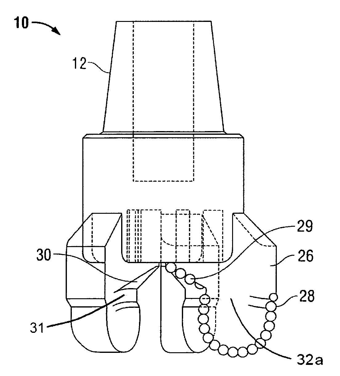
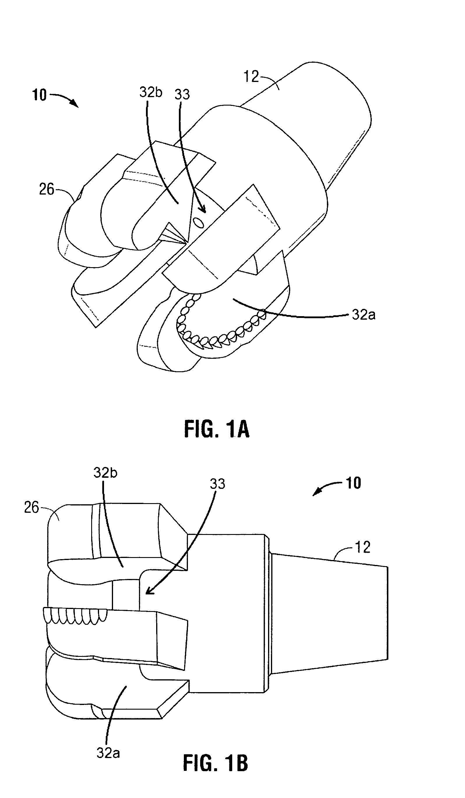
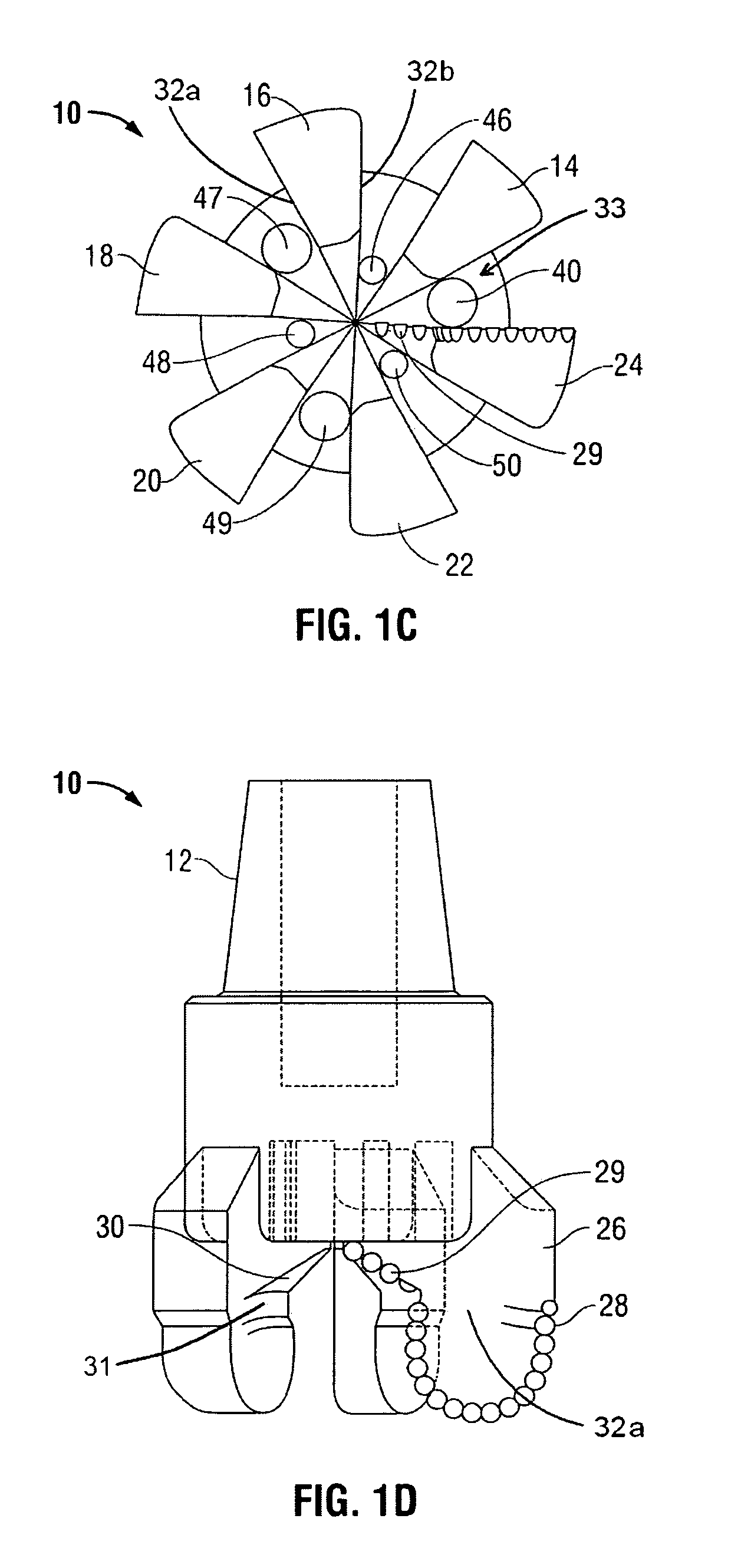
[0034]Referring now to the drawings in more detail, FIGS. 1A, 1B, 1C and 1D illustrate a drill bit 10 having a threaded pin end 12 which can be threaded into the box end of a joint of drill pipe (not illustrated). Each of the blades 14, 16, 18, 20, 22 and 24 has its own wear gauge pad 26. Each of the blades is further shown comprising a side surface 32a and 32b, which defines an open space or a channel 33 therebetween.

[0035]Each of the blades has a row of PDC cutters 28. It should appreciated that for each of the blades, the row of PDC cutters 28 starts off from the wear pad 26, as best illustrated in FIG. 1D. The rotation of the bit causes the u-shape portion of the row of PDC cutters to drill around what ends up being the core which is uncut until later when the PDC cutters in the relief portion 30 cause the core stump to disintegrate and be drilled out. The PDC cutters in the relief section is identified by the numeral 29. The relief section cutters 29 are also illustrated in FIG...


PUM


Abstract

A drill bit having fixed Polycrystalline Diamond Compact cutters is used to drill a borehole having a core stump therein. A plurality of additional fixed Polycrystalline Diamond Compact cutters are disposed in the dome of the bit and are usable to concentrate stresses in the top end of the core stump to facilitate the cutting down of the core stump.

Description

FIELD OF THE INVENTION[0001]This invention relates generally to the use of coring bit technology in combination with a drill bit used for drilling an earth borehole, and more particularly, to a combination coring bit and drill bit using fixed cutter PDC cutters for both functions.PRIOR ART[0002]It is known in the art of drilling earth boreholes to combine the features of a rotary cone drill bit with a dome area cutter insert, for example, as described in U.S. Pat. No. 5,695,019 to James M. Shamburger, Jr. which issued on Dec. 9, 1997.[0003]In the field of exploration and production of oil and gas, one type of drill bit, sometimes referred to as a rock bit, is used for drilling earth boreholes and is commonly known as a rotary cone drill bit. The typical rotary cone drill bit employs a multiplicity of rolling cone cutters rotatably mounted to extend downwardly and inwardly with respect to the central access of the drill bit. Typically, the rolling cone cutters may have milled teeth o...

Claims


Application Information

Patent Timeline
Patent Type & Authority Patents(United States)
IPC IPC(8): E21B10/02E21B10/48E21B10/04
CPCE21B10/48E21B10/04E21B10/54
Inventor SHAMBURGER, JAMES
Owner DIAMANT DRILLING SERVICES
Why Eureka
Try Eureka