Gate valve

a gate valve and valve body technology, applied in the direction of valve arrangements, lift valves, slide valves, etc., can solve the problems of complex structure of the valve body, inability to reliably separate spaces, and inability to obtain high reliability

Active Publication Date: 2012-06-28
ULVAC INC
View PDF11 Cites 11 Cited by
  • Summary
  • Abstract
  • Description
  • Claims
  • Application Information

AI Technical Summary

Benefits of technology

[0038]In the gate valve of the aspect of the invention, the valve plate is constituted of the fixed valving section and the movable valving section.
[0039]Furthermore, the first biasing section causes the movable valving section to transfer toward the first opening portion, causes the movable valving section to come into contact with the inner surface, presses the movable valving section onto the inner surface, and closes the flow passage.
[0040]Additionally, the second biasing section causes the movable valving section to transfer toward the second opening portion, separates the movable valving section from the inner surface, and thereby releases the flow passage.
[0041]With this configuration, it is possible to form a valving element by use of one valve plate and two biasing sections.
[0042]Additionally, the first biasing section transfers the movable valving section and can directly and reliably close the gate valve.
[0043]Moreover, the second biasing section transfers the movable valving section and can directly and reliably open the gate valve.

Problems solved by technology

If the rigidity in the valve plate is insufficient, there are problems in that it is not possible to reliably separate spaces and a high level of reliability cannot be obtained.
Since this connection structure and the actuator are individual components, there is a problem in that the structure of the valving element becomes complicated.
Moreover, in a large-diameter valve, a cylinder which produces great power is necessary for resisting the back pressure, and there is a problem in that the valving element becomes larger.
For this reason, if this pressing force is insufficient, there are problems in that it is not possible to reliably separate spaces and a high level of reliability cannot be obtained.
In addition, in order to resist the back pressure in a large-diameter valve or to apply a valve plate, a seal ring plate, a flange having a particular kind of configuration, it is necessary to arrange a plurality of actuator components excluding a cylinder, and there is a problem in that the constitution of the gate valve becomes complicated.

Method used


Image

  • Gate valve
  • Gate valve
  • Gate valve

Examples


first embodiment

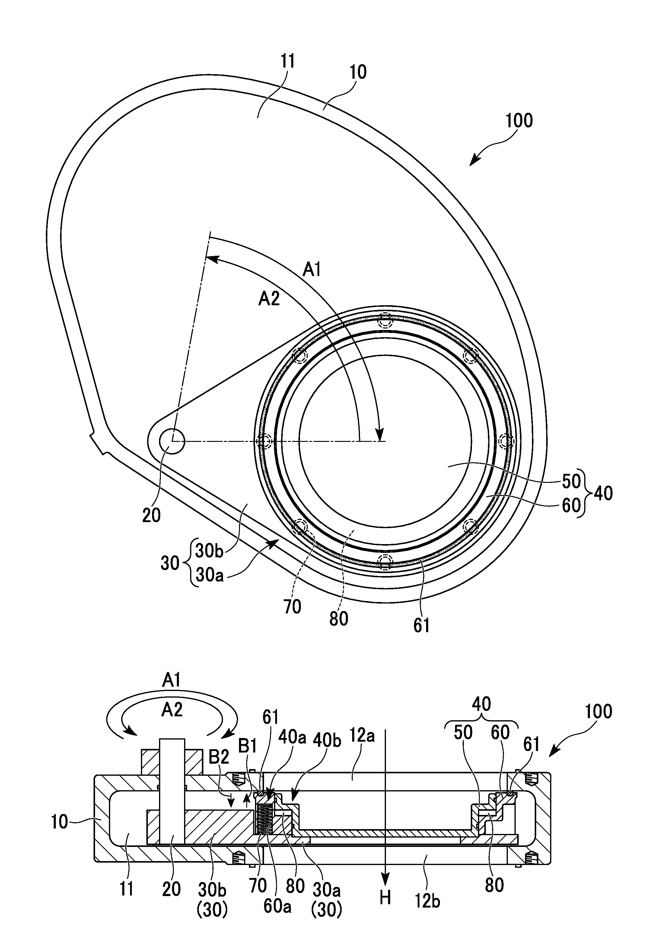
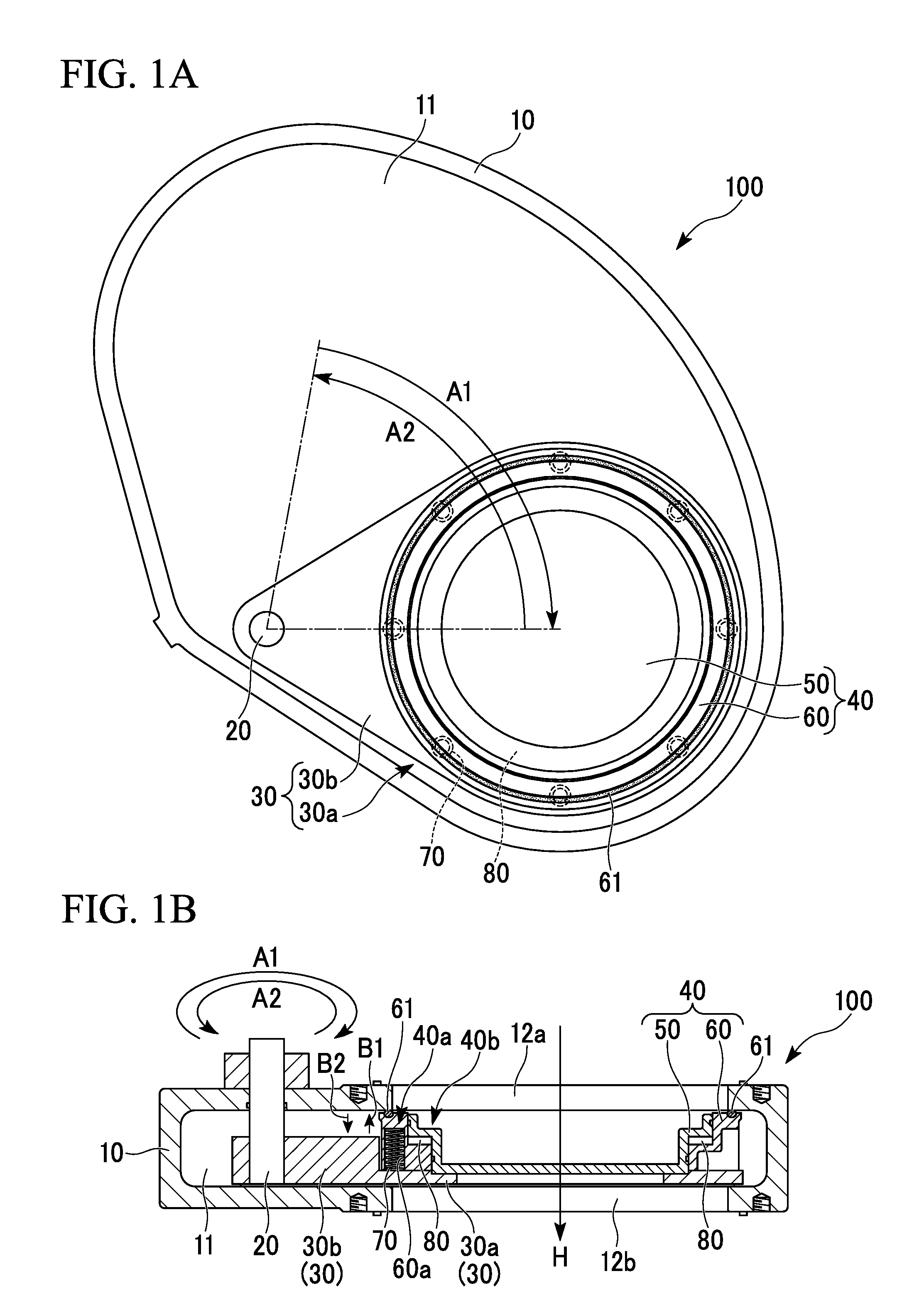
[0062]FIGS. 1A and 1B are views illustrating the constitution of a gate valve of a first embodiment of the invention.

[0063]FIG. 1A is a horizontal cross-sectional view showing the gate valve, and FIG. 1B is a vertical cross-sectional view showing the gate valve in the case where a valving element is placed at a valve opening-closing position.

[0064]A gate valve 100 of the first embodiment is provided with a valve box 10, a rotation shaft 20, a support body 30, a valve plate 40, first biasing sections 70, and a second biasing section 80.

[0065]The support body 30 and the valve plate 40 constitute the valving element.

[0066]Additionally, the valve plate 40 is constituted of the fixed valving section 50 (fixed valve plate section) and the movable valving section 60 (movable valve plate section).

[0067][Pendulum Gate Valve]

[0068]The gate valve 100 of the first embodiment is a pendulum gate valve.

[0069]When the rotation shaft 20 is rotated in the direction (direction which intersects with th...

second embodiment

[0209]FIG. 3 shows a gate valve of a second embodiment of the invention, and is an enlarged vertical cross-sectional view showing the portion at which a fixed valving section is fitted to a movable valving section.

[0210]In FIG. 3, identical symbols are used for the elements which are identical to those of FIGS. 1A and 1B or FIG. 2, and the explanations thereof are omitted or simplified.

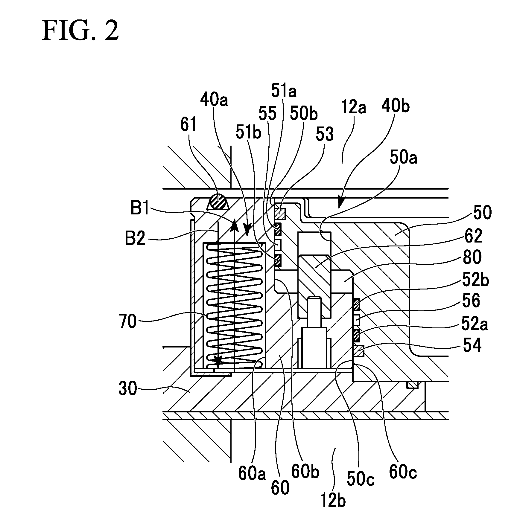
[0211]In a gate valve of a second embodiment, the portion at which the fixed valving section 50 and the movable valving section 60 of the above-described gate valve 100 of the first embodiment (refer to FIGS. 1A, 1B, or 2) are fitted to each other is modified, and the thickness of the valve plate 40 decreases.

[0212]In the structure of the valve plate 40 of the aforementioned first embodiment, as shown in FIG. 2, the outer-crank portion formed around the outer-periphery of the fixed valving section 50 is fitted into the inner-crank portion formed on the inner-periphery of the movable valving section 60...

third embodiment

[0222]FIGS. 4A and 4B are views illustrating the constitution of the gate valve of the third embodiment of the invention.

[0223]FIG. 4A is a horizontal cross-sectional view showing a gate valve, and FIG. 4B is a vertical cross-sectional view showing the gate valve when the valving element is disposed at the valve opening-closing position.

[0224]In FIGS. 4A and 4B, identical symbols are used for the elements which are identical to those of FIGS. 1A and 1B, and the explanations thereof are omitted or simplified.

[0225]A gate valve 300 of a third embodiment is provided with a valve box 10a, a valve rod 25, a support body 30, a valve plate 40, first biasing sections 70 (spring), and a second biasing section 80 (air cylinder).

[0226]The support body 30 and the valve plate 40 constitute the valving element.

[0227]Additionally, the valve plate 40 is constituted of a fixed valving section 50 and a movable valving section 60.

[0228][Direct Acting Gate Valve]

[0229]The gate valve 300 of the third em...


PUM


Abstract

A gate valve includes: a valve box; a support body disposed inside a hollow portion; a valve plate including a fixed valving section, a movable valving section sliding in a direction in which a flow passage is extended, a first peripheral region; and a second peripheral region; a first biasing section disposed at the first peripheral region, allowing the movable valving section to move toward a first opening portion, allowing the movable valving section to come into contact with an inner surface, pressing the movable valving section onto the inner surface, and closing the flow passage; and a second biasing section disposed at the second peripheral region, allowing the movable valving section to move toward a second opening portion, and releasing the flow passage by separating the movable valving section from the inner surface.

Description

CROSS-REFERENCE TO RELATED APPLICATION[0001]This is the U.S. National Phase Application under 35 U.S.C. §371 of International Patent Application No. PCT / JP2010 / 065144 filed Sep. 3, 2010, which designated the United States and was published in a language other than English, which claims the benefit of Japanese Patent Application No. 2009-204070 filed on Sep. 3, 2009, both of them are incorporated by reference herein. The International Application was published in Japanese on Mar. 10, 2011 as WO2011 / 027861 A1 under PCT Article 21(2).BACKGROUND OF THE INVENTION[0002]1. Field of the Invention[0003]The present invention relates to a gate valve which is suitable for use in a pendulum valve, a direct acting valve, a door valve, or the like, which slidably operates a valve plate in addition to an operation of opening and closing a flow passage using the valve plate.[0004]Particularly, the present invention relates to a gate valve which separates (closes) flow passage communicating two space...

Claims


Application Information

Patent Timeline
Patent Type & Authority Applications(United States)
IPC IPC(8): F16K3/30
CPCF16K1/2085F16K3/188F16K3/10F16K3/18F16K51/02
Inventor NAKAMURA, KYUZOSHIBAYAMA, KOUJIWADA, SHINICHISAKODA, SEIYA
Owner ULVAC INC
Why Eureka
Try Eureka