Automatic choke apparatus for carburetor

Active Publication Date: 2012-06-28
HONDA MOTOR CO LTD
View PDF1 Cites 9 Cited by
  • Summary
  • Abstract
  • Description
  • Claims
  • Application Information

AI Technical Summary

Benefits of technology

[0006]The present invention has been made with the foregoing situation taken into consideration. The present invention is directed toward providing an automatic choke apparatus that prevents a choke valve from freezing up in a fully-closed state when an engine is stopped in an extremely low temperature environment.
[0008]With the first feature of the present invention, the choke valve is set in the semi-opened position when the engine is stopped, and in the fully-closed position when the engine starts to be cranked. For this reason, even if a valve shaft of the choke valve freezes up while the engine is being stopped (i.e., in the semi-opened position), the amount of air does not become smaller than needed immediately after the engine is started, and the engine stall is avoided. Accordingly, the marketability can be enhanced.
[0010]With the second feature of the present invention, the electric actuator is commonly used between the throttle valve opening / closing mechanism for opening and closing the throttle valve and the choke valve opening / closing mechanism. For this reason, it is possible to reduce the number of parts, and to build the automatic choke apparatus in a compact size. Further, the choke valve opening / closing mechanism operates the choke valve between the fully-closed position and the semi-opened position in accordance with an opening degree of the throttle valve while the engine is being warmed up. For this reason, the engine can be started in a satisfactory condition by matching the opening degree of the choke valve with the opening degree of the throttle valve while the engine is being warmed up.

Problems solved by technology

For this reason, the valve shaft of the choke valve may freeze up in the fully-closed state when the automatic choke apparatus is used on a carburetor of a general-purpose engine installed in snowplow trucks and the like, which are used in an extremely low temperature, high humidity environment.
This adversely affects the marketability.

Method used


Image

  • Automatic choke apparatus for carburetor
  • Automatic choke apparatus for carburetor
  • Automatic choke apparatus for carburetor

Examples


Embodiment Construction

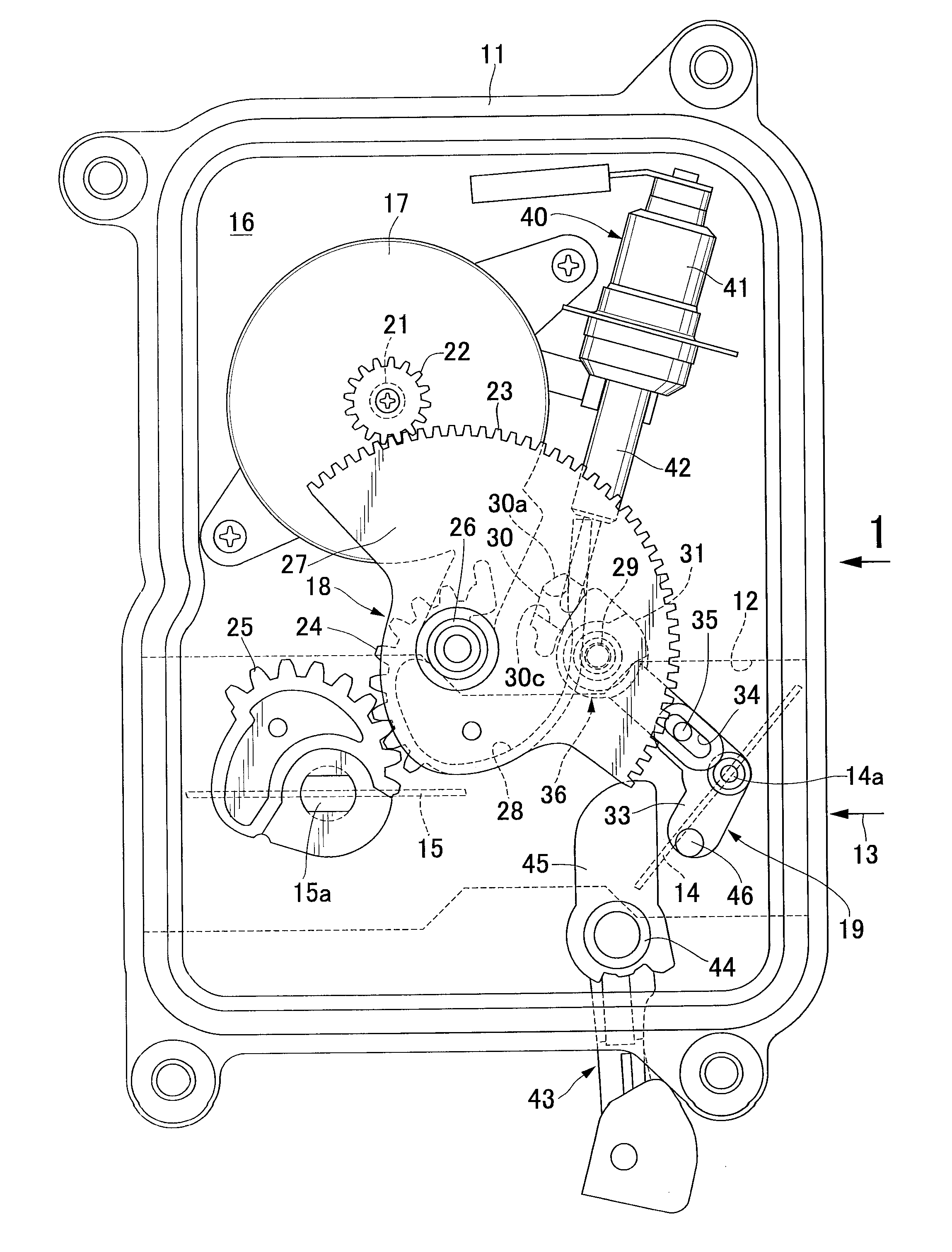
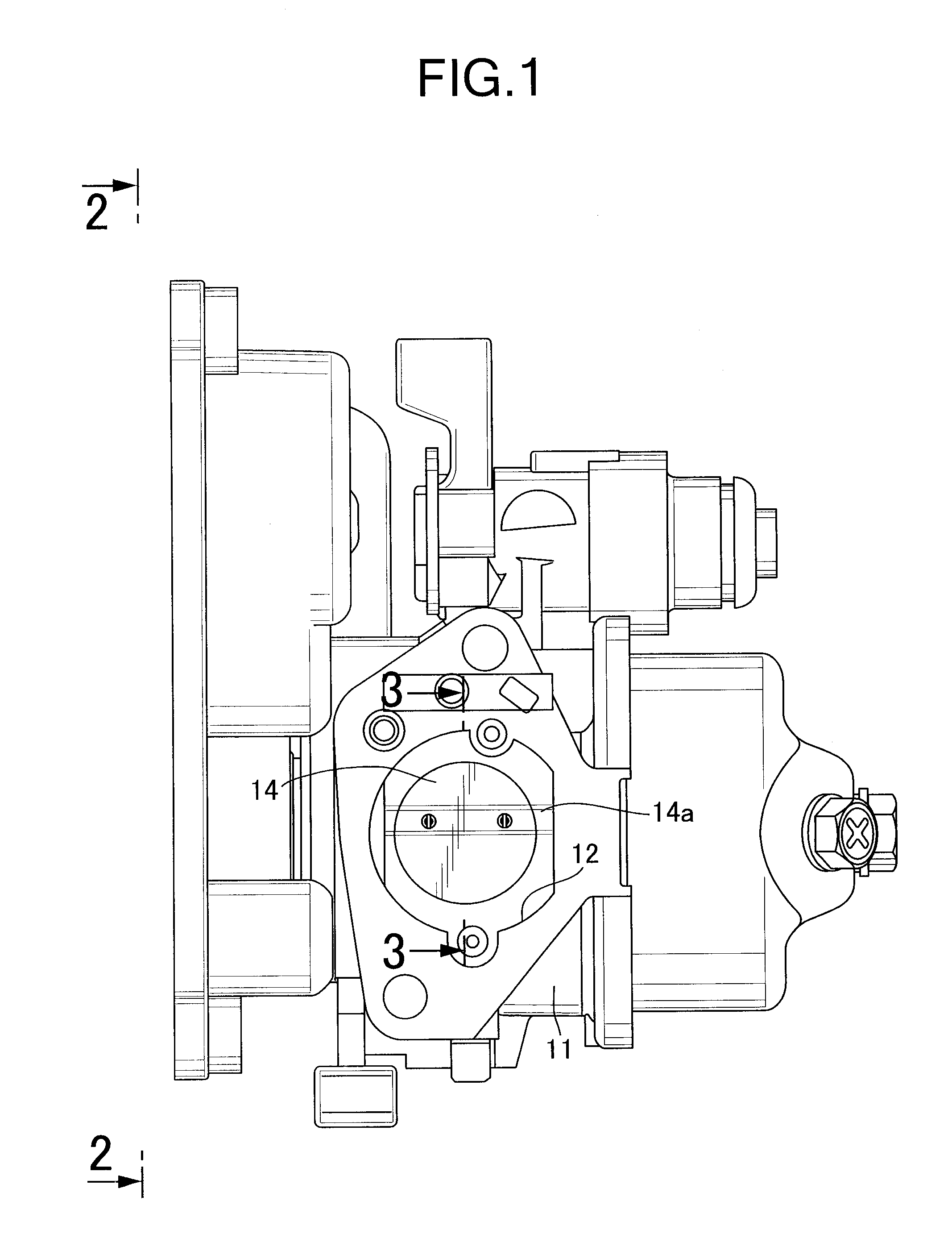
[0026]Descriptions will be hereinbelow provided for an embodiment of the present invention while referring to the attached drawings. First of all, in FIGS. 1 to 3, the carburetor is for a general-purpose engine to be mounted on a snowplow truck or the like, which is used in an extremely low temperature, high humidity environment, and, from the upstream side in an air intake direction 13, a butterfly-type choke valve 14 and a butterfly-type throttle valve 15 are placed, in this order, in an air intake path 12 provided in a carburetor main body 11. The choke valve 14 is fixedly attached to a choke valve shaft 14a which is rotatably supported by the carburetor main body 11 in a way that makes the choke valve shaft 14a traverse the air intake path 12. The throttle valve 15 is fixedly attached to a throttle valve shaft 15a which is rotatably supported by the carburetor main body 11 in a way that makes the throttle valve shaft 15a traverse the air intake path 12.

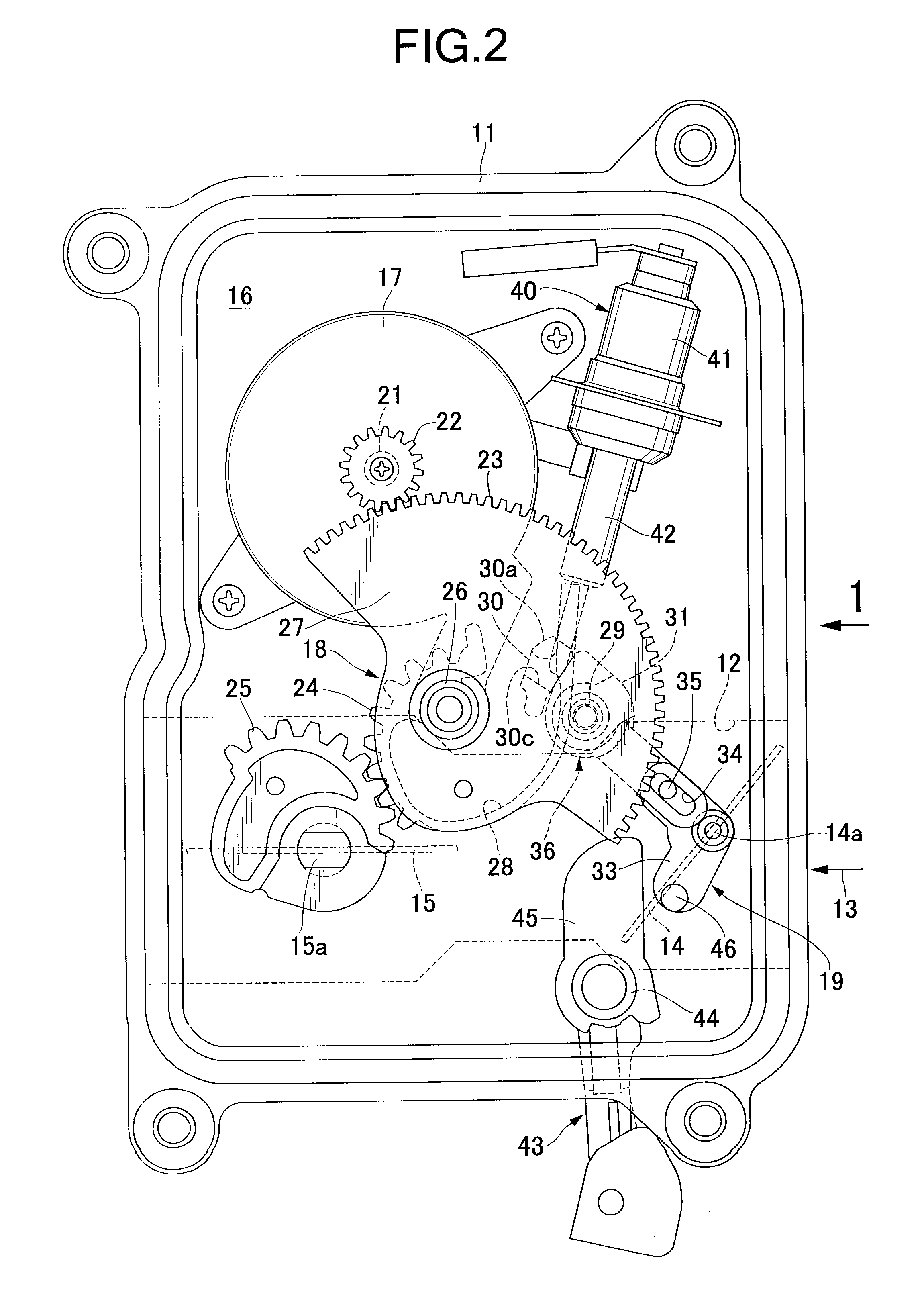
[0027]As shown in FIG. 2, ...


PUM

PropertyMeasurementUnit
Temperatureaaaaaaaaaa

Abstract

An automatic choke apparatus for a carburetor includes an electric actuator, a choke valve opening / closing mechanism configured to open and close a choke valve by being driven by a power exerted by the electric actuator, and a controller configured to control operation of the electric actuator. The controller, to which a battery supplies electric power, operates the electric actuator and the choke valve opening / closing mechanism in order that, when the engine is stopped, the choke valve is set in a semi-opened position and, when the engine starts to be cranked, the choke valve is set in a fully-closed position. Accordingly, it is possible to prevent the choke valve from freezing up in the fully-closed state in a case where the engine is stopped under an extremely low temperature environment.

Description

BACKGROUND OF THE INVENTION[0001]1. Field of the Invention[0002]The present invention generally relates to an automatic choke apparatus for a carburetor and, more particularly, to an automatic choke apparatus for a carburetor that is suitable for use in a general-purpose engine.[0003]2. Description of the Related Art[0004]Japanese Patent Application Laid-open No. 2007-2752 teaches an automatic choke apparatus for a carburetor that is designed to drive a choke valve to open and close using power exerted by an electric actuator.[0005]Meanwhile, the automatic choke apparatus for a carburetor, which is disclosed by Japanese Patent Application Laid-open No. 2007-2752, sets the choke valve into a fully-closed state when the engine is stopped. For this reason, the valve shaft of the choke valve may freeze up in the fully-closed state when the automatic choke apparatus is used on a carburetor of a general-purpose engine installed in snowplow trucks and the like, which are used in an extreme...

Claims


Application Information

Patent Timeline
IPC IPC(8): F02M1/10F02M9/08F02M1/04
CPCF02D9/1025F02D41/067F02M1/10F02D2009/0249F02D2009/0247
Inventor ARAI, TETSUYA
Owner HONDA MOTOR CO LTD
Why Eureka
Try Eureka