Electric rotating machine

a rotating machine and electric technology, applied in the direction of dynamo-electric machines, electrical equipment, commutators, etc., can solve the problems of increasing problems and lowering the vibration resistance of the coil end on the welded side, and achieve the effect of improving the vibration resistan

Active Publication Date: 2012-06-28
DENSO CORP
View PDF11 Cites 33 Cited by
  • Summary
  • Abstract
  • Description
  • Claims
  • Application Information

AI Technical Summary

Benefits of technology

[0012]According to the exemplary embodiment, there is provided an electric rotating machine having a stator winding constituted of U-shaped conductor segments connected in series by welding at their welded portions opposite to their turn portions, which is improved in vibration-resistance at the coil end on the side of the welded portions.

Problems solved by technology

However, the above conventional electric rotating machine has a problem in that since the pitch of the coil end on the welded side of the conductor segments opposite to the coil end on the side of the turn portions is set to 180 degrees, the distance between the end surface of the stator core and each welded portion is large, the vibration-resistance of the coil end on the welded side is lowered.
This problem increases when the conductor segments are thick and heavy to carry a large current.

Method used


Image

  • Electric rotating machine
  • Electric rotating machine
  • Electric rotating machine

Examples


Embodiment Construction

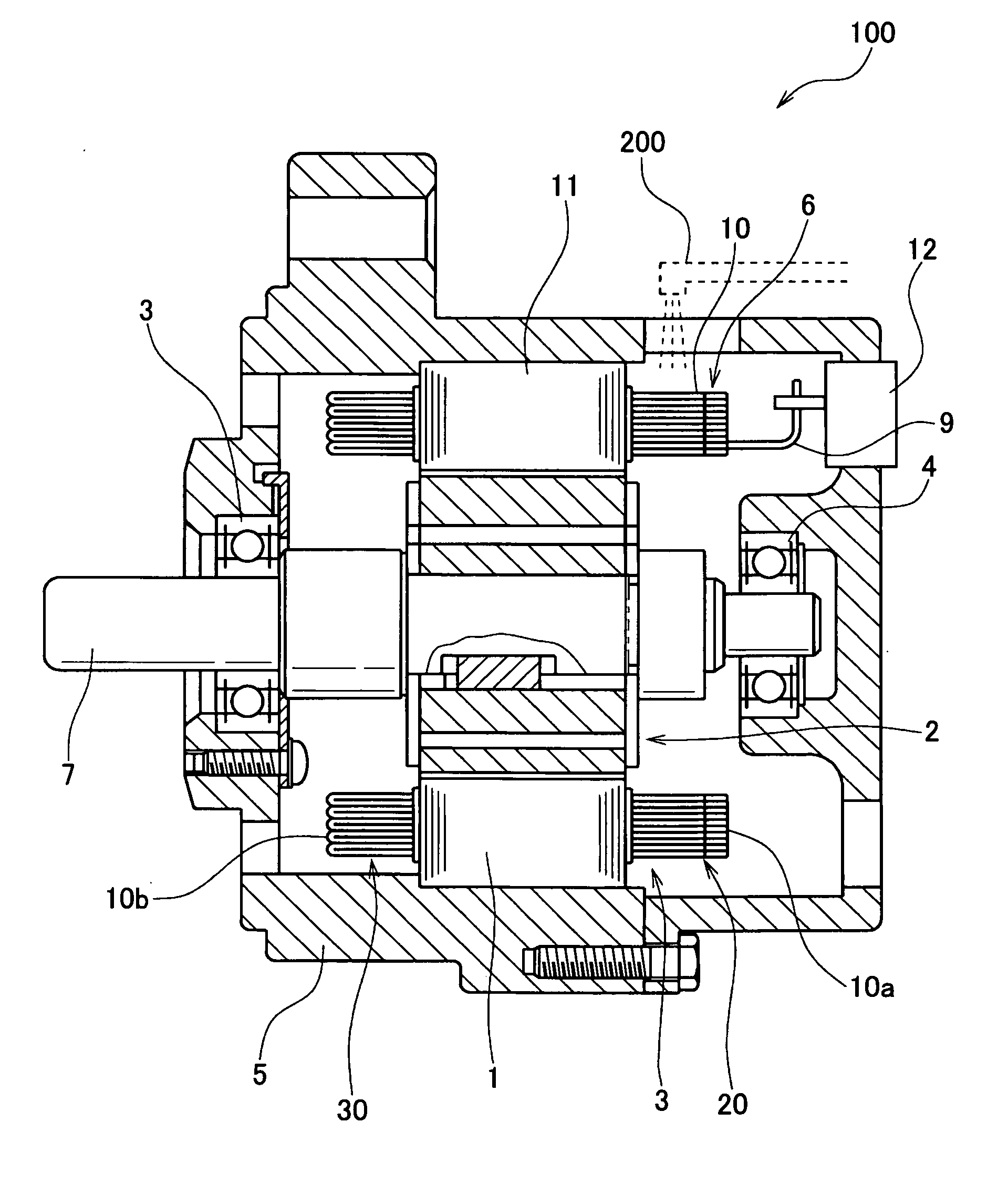
[0021]FIG. 1 is a cross-sectional view of a vehicle-use electric rotating machine 100 according to an embodiment of the invention. As shown in FIG. 1, the electric rotating machine 100 includes a stator 1, a rotor 2, a front bearing 3, a rear bearing 4 and a frame 5.

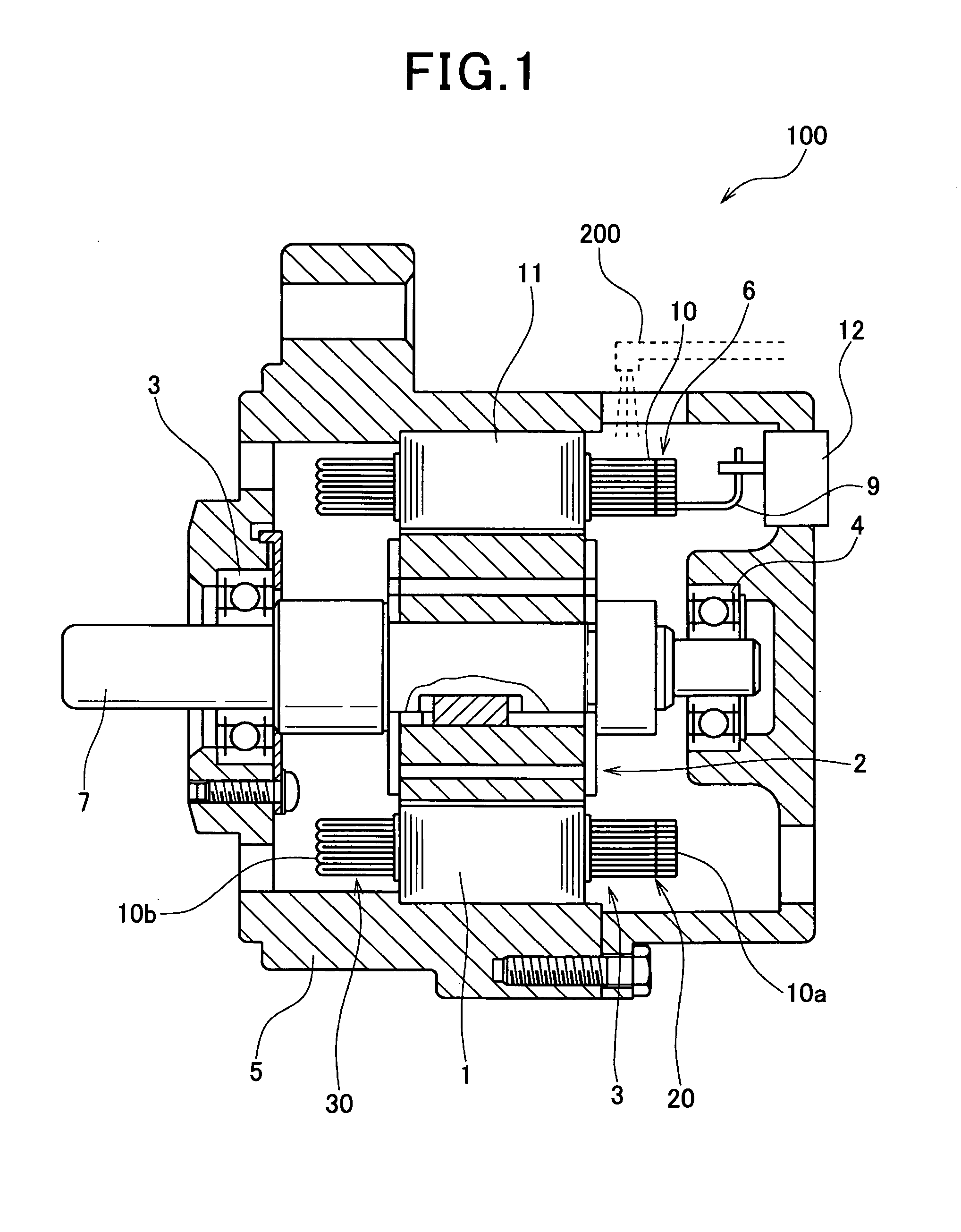
[0022]The stator 1 includes a cylindrical stator core 11 with slots formed along its circumferential direction, and conductor segments 10 constituting a stator winding 6 as a multiple star-connected phase winding (three-phase winding including U-phase, V-phase and W-phase windings in this embodiment).

The stator core 11 is formed as a laminated core fabricated by stacking laminated steel sheets of a predetermined thickness. The stator winding 6 is supplied with a current from a three-phase inverter control circuit (not shown).

[0023]The rotor 2, which is disposed inside the stator 1, is embedded with permanent magnets. The rotating shaft 7 of the rotor 2 is rotatably supported by the front bearing 3 and the rear bearing 4....


PUM


Abstract

The stator of the electric rotating machine includes a stator winding constituted of a plurality of U-shaped conductor segments each including a turn portion and two straight portions, the U-shaped conductor segments being connected in series by welding at welded portions formed in ends of the straight portions, and a stator core formed with slots, the straight portions of each U-shaped conductor segment being accommodated in corresponding two of the slots. The welded side slot pitch as an interval of the corresponding two of the slots on the side opposite to the turn portions is narrower than the N-S magnetic pole pitch of the rotor. The stator winding includes overlapped wire wrapping sections each constituted of the U-shaped conductor segments accommodated in the corresponding two of the slots, and crossover wires disposed on the side of the welded portions for connecting the overlapped wire wrapping sections.

Description

[0001]This application claims priority to Japanese Patent Applications No. 2010-292982 filed on Dec. 28, 2010, No. 2011-180135 filed on Aug. 22, 2011, and No. 2011-269141 filed on Dec. 8, 2011, the entire contents of which are hereby incorporated by reference.BACKGROUND OF THE INVENTION[0002]1. Field of the Invention[0003]The present disclosure relates to an electric rotating machine mounted on a vehicle such as a passenger car.[0004]2. Description of Related Art[0005]There is known an electric rotating machine including a stator winding constituted of U-shaped conductor segments joined by welding to one another. For example, refer to Japanese Patent Application Laid-open No. 2003-209956. The electric rotating machine disclosed in this patent document is increased in rigidity of the coil end on the side of the turn portions to improve vibration-resistance by setting the pitch of the coil end formed by the turn portions of the conductor segments on the side of the turn portions narro...

Claims


Application Information

Patent Timeline
Patent Type & Authority Applications(United States)
IPC IPC(8): H02K3/04
CPCH02K15/0081H02K3/28
Inventor HISADA, TOMOKAZU
Owner DENSO CORP
Why Eureka
Try Eureka