
Lighting apparatus and lighting fitting

a technology of light fittings and light fittings, which is applied in the direction of lighting and heating apparatus, semiconductor devices for light sources, transportation and packaging, etc., can solve the problems of low heat tolerance of leds, shortening the intrinsic life of leds, and deteriorating elements, etc., and achieves high accuracy.

Active Publication Date: 2012-06-28
DENSO CORP
View PDF5 Cites 42 Cited by
  • Summary
  • Abstract
  • Description
  • Claims
  • Application Information

AI Technical Summary

Benefits of technology

[0010]An embodiment provides a lighting apparatus and a lighting fitting which enable measurement of temperature of light sources with high accuracy.

Problems solved by technology

LEDs are advantageous in that maximum quantity of light is available upon turning on the LEDs but are disadvantageous in that LEDs have a low tolerance for heat.
As a result, the element of the LED will be deteriorated to make the life-span of the LED shorter than the intrinsic life-span, or reduce the quantity of light emitted from the LED.
The method set forth above for measuring temperature of LEDs via a heat sink and the air in the interior of a lighting fitting has suffered from a problem that the measurement is easily affected by external factors because the path used for temperature transmission is long, and thus it is difficult to accurately measure the temperature of the LEDs.
In addition, the method has also suffered from a problem that, when the temperature of the LEDs changes, it takes time to measure the change of the temperature because the speed of transmission of the LEDs' temperature is slow.

Method used


Image

  • Lighting apparatus and lighting fitting
  • Lighting apparatus and lighting fitting
  • Lighting apparatus and lighting fitting

Examples


first embodiment

[0029]With reference to the accompanying drawings, hereinafter are described some embodiments of the present invention.

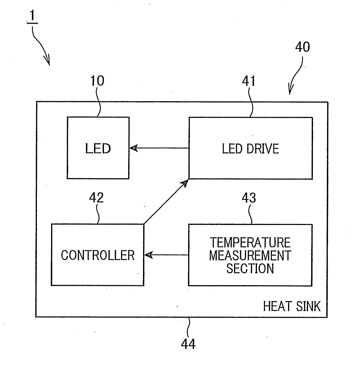
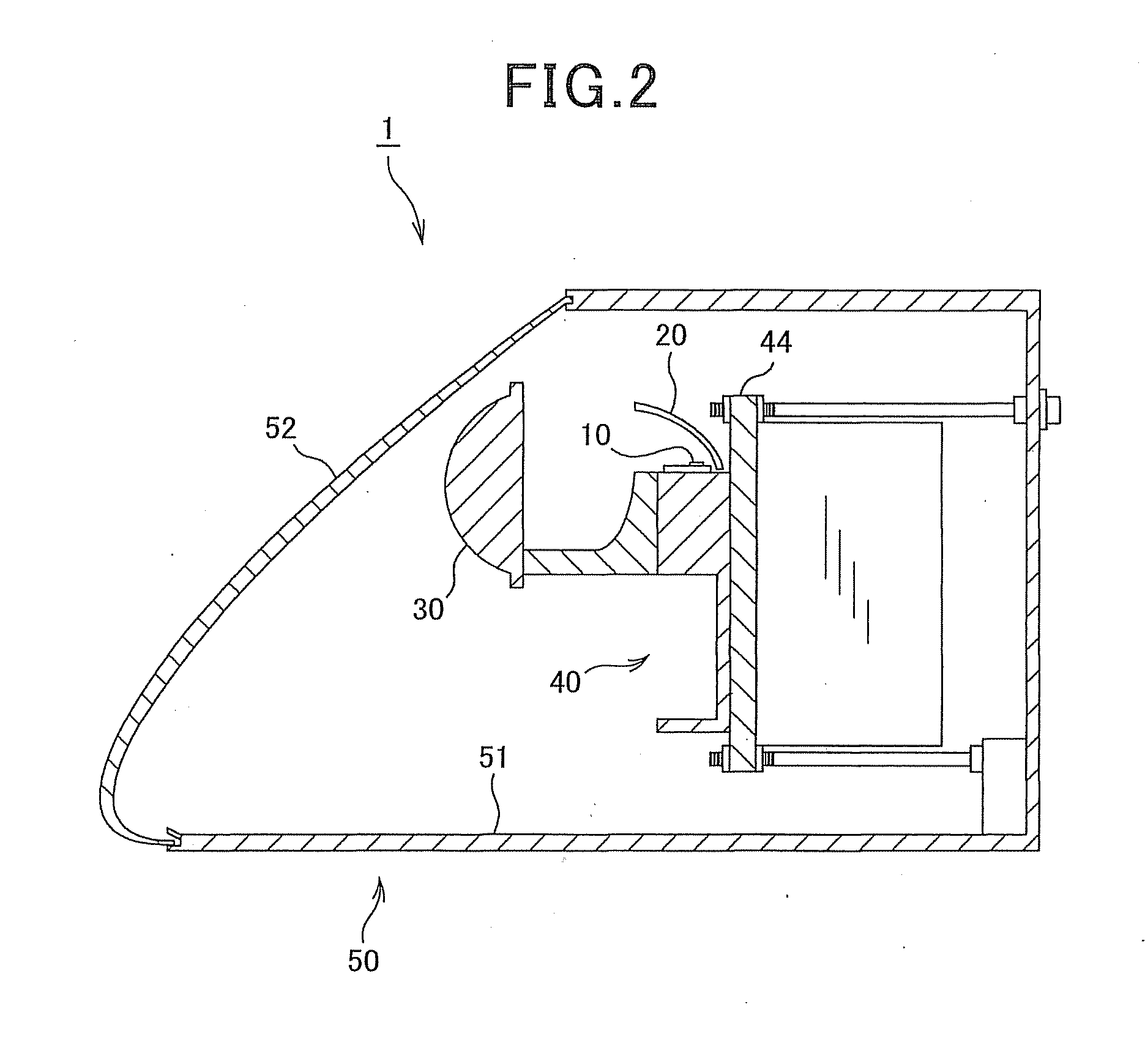
[0030]Referring to FIGS. 1 to 4, first, a vehicle lighting fitting according to a first embodiment of the present is described. FIG. 1 is a block diagram illustrating the configuration of a vehicle lighting fitting 1 according to the first embodiment. FIG. 2 is a cross-sectional view illustrating the configuration of the vehicle lighting fitting 1 illustrated in FIG. 1. FIG. 3 is a perspective view illustrating the configuration of a lighting apparatus 40 illustrated in FIG. 1 or 2. FIG. 4 is a cross-sectional view illustrating the configuration of the lighting apparatus 40 illustrated in FIG. 3.

[0031]The vehicle lighting fitting 1 (hereinafter also just referred to as “lighting fitting 1”) of the present embodiment is used as each of headlights for illuminating the forward direction of a vehicle equipped with the lighting fittings 1. Each of the headlights uses LED...

second embodiment

[0067]Referring now to FIGS. 7 and 8, hereinafter is described a second embodiment of the present invention.

[0068]A vehicle lighting fitting of the second embodiment has a basic configuration similar to that of the first embodiment. The second embodiment however is different from the first embodiment in that a fan is provided to cool the LEDs and the heat sink. In the present embodiment, the configuration and control of the fan is described referring to FIGS. 7 and 8 and description such as of other components is omitted.

[0069]FIG. 7 is a block diagram illustrating the configuration of a vehicle lighting fitting 101 according to the second embodiment. FIG. 8 is a flow diagram illustrating drive control of a fan 162 in the lighting fitting 101 illustrated in FIG. 7. As shown in FIG. 7, the lighting fitting 101 of the present embodiment includes the LEDs 10, the lighting apparatus 40, a fan drive 161 and the fan 162.

[0070]The fan drive 161 supplies current for driving the fan 162 and ...

third embodiment

[0080]Referring to FIGS. 9 and 10, hereinafter is described a third embodiment of the present invention.

[0081]A vehicle lighting fitting of the third embodiment has a basic configuration similar to that of the first embodiment. However, the third embodiment is different from the first embodiment in that the controller determines whether or not a failure has occurred in the LEDs. Referring to FIGS. 9 and 10, the present embodiment is described focusing on a process of failure determination made by the controller, omitting description such as of other components.

[0082]FIG. 9 is a block diagram illustrating the configuration of a vehicle lighting fitting 201 according to the third embodiment. FIG. 10 is a flow diagram illustrating the process of determining the occurrence of failure in the LEDs 10 of the lighting fitting 201 illustrated in FIG. 9. As shown in FIG. 9, the lighting fitting 201 of the present embodiment includes the LEDs 10, the lighting apparatus 40, a controller 242 and...


PUM


Abstract

A lighting apparatus is provided which includes a drive section which applies electric current to a light source which is a semiconductor element emitting light with application of electric current, at least one heat sink which is mounted with the light source and transfers heat generated by the emission of the light source, and a temperature measurement section which is mounted to the heat sink and measures temperature of the heat sink which is used for estimating temperature of the light source. The light source and the drive section are mounted to the same heat sink or to the heat sinks which are thermally coupled to each other.

Description

CROSS-REFERENCE TO RELATED APPLICATION[0001]This application is based on and claims the benefit of priority from earlier Japanese Patent Application No. 2010-290905 filed Dec. 27, 2010, the description of which is incorporated herein by reference.BACKGROUND OF THE INVENTION[0002]1. Technical Field of the Invention[0003]The present invention relates to a lighting apparatus for lighting a light source and to a lighting fitting, and in particular to a lighting apparatus which is favorably used with LEDs (light emitting diodes) that serve as light sources and to a lighting fitting.[0004]2. Related Art[0005]Recently, semiconductor light sources, such as LEDs, have come into practical use as light sources of lighting fittings. Thus, lighting fittings using LEDs as light sources have come to be widely used. For example, as disclosed in JP-A-2007-035547, vehicle headlights are also suggested to use LEDs as light sources.[0006]The life-span of LEDs is long compared to that of incandescent la...

Claims


Application Information

Patent Timeline
Patent Type & Authority Applications(United States)
IPC IPC(8): H05B37/02F21W107/10H05B44/00
CPCF21V23/007F21V29/763F21Y2101/02H05B33/0851H05B33/0854B60Q1/0023B60Q1/085B60Q1/143B60Q11/005F21S48/1104F21S48/1159F21S48/328B60Q2300/14F21S48/325F21V29/71F21V29/02F21Y2115/10F21S41/19F21S45/43F21S45/47F21S41/148F21S41/151H05B45/18F21V29/60
Inventor NISHITANI, DAISUKENISHII, TAKAHITOKAMIZONO, TSUTOMUNAKANO, TAKAHIRO
Owner DENSO CORP
Features
  • Generate Ideas
  • Intellectual Property
  • Life Sciences
  • Materials
  • Tech Scout
  • Unparalleled Data Quality
  • Higher Quality Content
  • 60% Fewer Hallucinations
Learn More