Optical fiber connector and method of manufacturing the same

Inactive Publication Date: 2012-06-28
GLORY SCI
View PDF6 Cites 1 Cited by
  • Summary
  • Abstract
  • Description
  • Claims
  • Application Information

AI Technical Summary

Benefits of technology

[0008]As described above, the optical fiber being molded in the insulating housing can omit an assembling procedure and omit dropping adhesives on the optical fiber. So that bubbles and air are disappeared, and deviation of relative position of the optical fiber is decreased. Consequently, the optical

Problems solved by technology

Secondly, inject molten materials into the mold.
Thirdly, separate the mold and then take out the optical fiber connector from the mold whe

Method used


Image

  • Optical fiber connector and method of manufacturing the same
  • Optical fiber connector and method of manufacturing the same
  • Optical fiber connector and method of manufacturing the same

Examples


Example

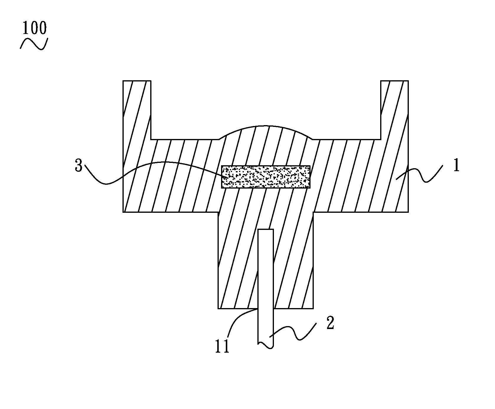
[0016]With reference to FIG. 2, a first optical fiber connector 100 according to an embodiment of the present invention includes a first insulating housing 1, a first optical fiber 2 and a transparent hetero substrate 3. The first insulating housing 1 defines a blind-hole 11. The first optical fiber 2 is exposed outside the first insulating housing 1 with one end portion of the first optical fiber 2 being insert molded in the first insulating housing 1 through the blind-hole 11. The transparent hetero substrate 3 is molded inside the first insulating housing 1. The transparent hetero substrate 3 is substantially perpendicular to the end portion of the first optical fiber 2 and spaced from an end edge of the end portion of the first optical fiber 2. A middle of the transparent hetero substrate 3 is substantially in alignment with the end portion of the first optical fiber 2.

[0017]Extinction ratio and intensity of light can be improved by means of molding the transparent hetero substr...


PUM


Abstract

An optical fiber connector includes an insulating housing, an optical fiber and a transparent hetero substrate. The optical fiber is exposed outside the insulating housing with one end portion molded in the insulating housing. The transparent hetero substrate is molded inside the insulating housing. The transparent hetero substrate is substantially perpendicular to the end portion of the optical fiber and spaced from an end edge of the end portion of the optical fiber. A middle of the transparent hetero substrate is substantially in alignment with the end portion of the optical fiber. The method of manufacturing the above-mentioned optical fiber connector is described hereinafter. Firstly, set an end portion of the optical fiber and a transparent hetero substrate in a mold. Secondly, inject molten materials into the mold. Thirdly, separate the mold and then take out the optical fiber connector from the mold when the mold is cooled.

Description

BACKGROUND OF THE INVENTION[0001]1. Field of the Invention[0002]The present invention generally relates to an optical fiber connector and a method of manufacturing the same, and more particularly to an optical fiber connector and a method of manufacturing the same capable of mounting an optical fiber in an insulating housing accurately.[0003]2. The Related Art[0004]Generally, an optical fiber is a slim transparent glass fiber or a transparent plastic fiber, and an optical fiber cable includes an optical fiber and a cover surrounding the optical fiber. Referring to FIG. 1, a traditional optical fiber connector 300 used for connecting optical fibers to transmit light signals between transmitter and receiver, includes an insulating housing 6 and an optical fiber 7 of an optical fiber cable (not shown). The insulating housing 6 defines a hole 61 at a bottom thereof. The optical fiber 7 is fastened in the hole 61 by means of injecting adhesives 8 between an outside of the optical fiber 7...

Claims


Application Information

Patent Timeline
IPC IPC(8): G02B6/36G02B6/26
CPCG02B6/32G02B6/3865G02B6/3696
Inventor LEE, YUAN-LINCHANG, CHIA-JUNGSHEN, WEIYANG, YUNG-HAN
Owner GLORY SCI
Why Eureka
Try Eureka