Brake control apparatus

Active Publication Date: 2010-10-28
ADVICS CO LTD
View PDF11 Cites 34 Cited by
  • Summary
  • Abstract
  • Description
  • Claims
  • Application Information

AI Technical Summary

Benefits of technology

[0036]As above, since the first and second target pressures are alternately switched from one to the other, it is possible to decrease the deviation between an actual differential pressure and an assumed differential pressure for the rear wheel, for which the control for the braking force distribution is carried out. Accordingly, the mod

Problems solved by technology

It would become more difficult to suppress a yaw torque applied to the vehicle and a vehicle spin may be likely to occur.
As a result, noise and vibration may be generated.
However, when the linear control is carried out for the pressure increase valve, deviation of differential pressure with respect to the driving current may be generated due to individual difference of the pressure increase valves.
As a result, a difference of the wheel cylinder pressure between the left and right wheels may become larger, and the differential pressure for the wheel cylinder pressure of the respective left and right wheels may not be controlled within a predetermined range, even when the select-low control is carried out on the μ-split road.
In particular, when the vehicle is running on the μ-split road, it may become difficult to sufficiently suppress the yaw torque to be applied to the vehicle and thereby it may become difficult to effectively prevent the possible vehicle spin.
Therefore, in such a case, it may be a problem that a desired braking force may not be obtained as a whole.
However, the desired differential pressure may not be generated, when the differential pressure actually generated is deviated from an expected value due to the

Method used


Image

  • Brake control apparatus
  • Brake control apparatus
  • Brake control apparatus

Examples


first embodiment

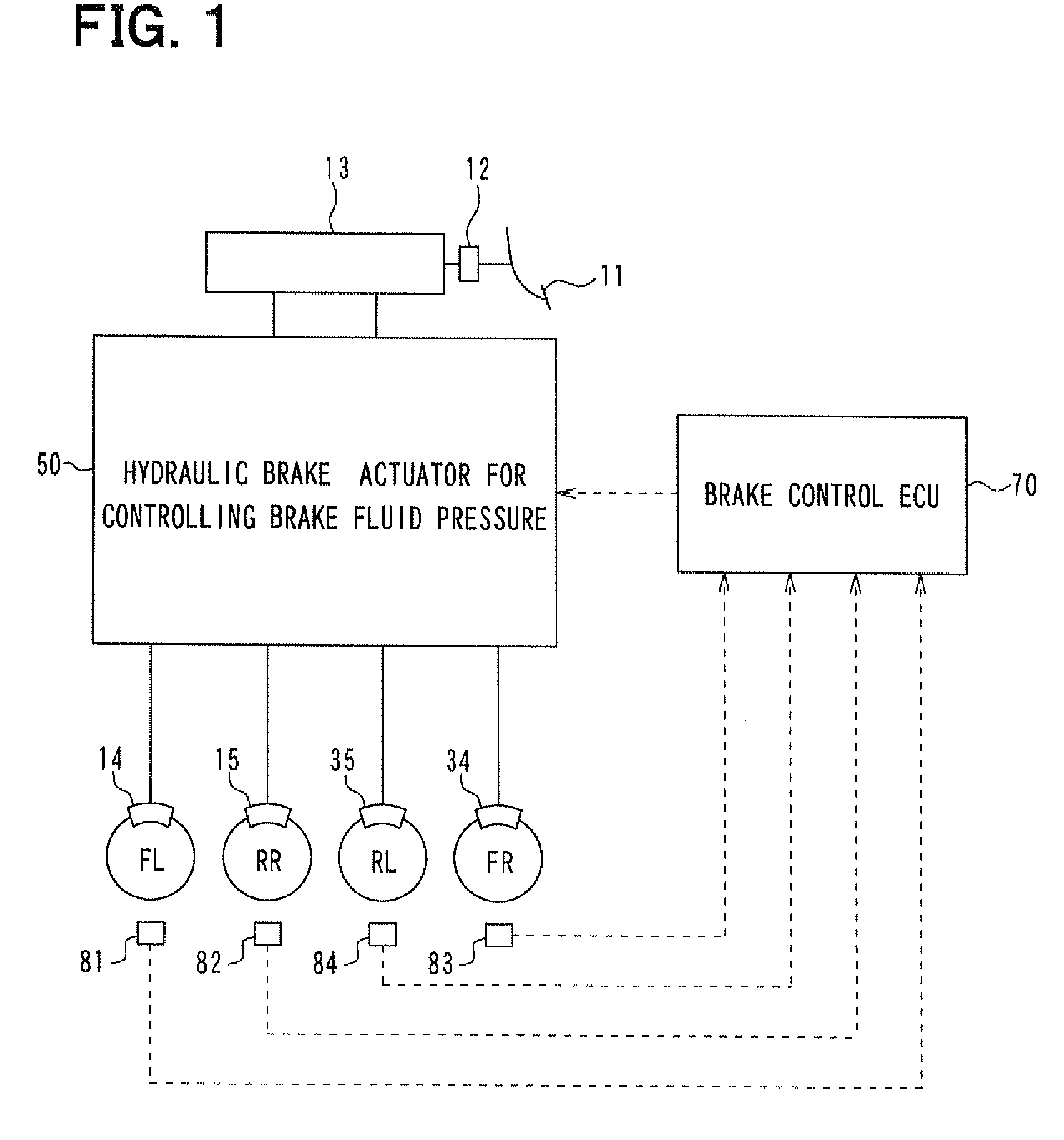
[0056]A first embodiment of the present invention will be explained. FIG. 1 shows a block diagram for a brake control apparatus 1 according to the present embodiment.

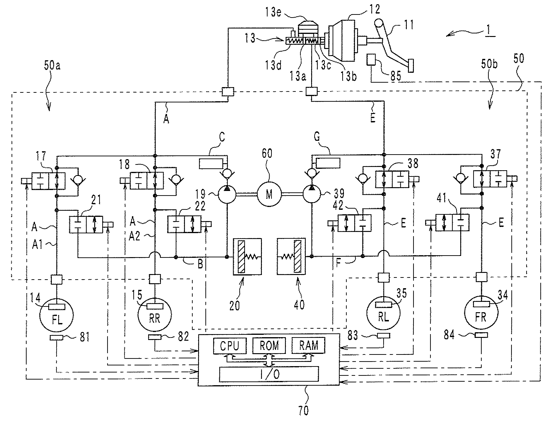
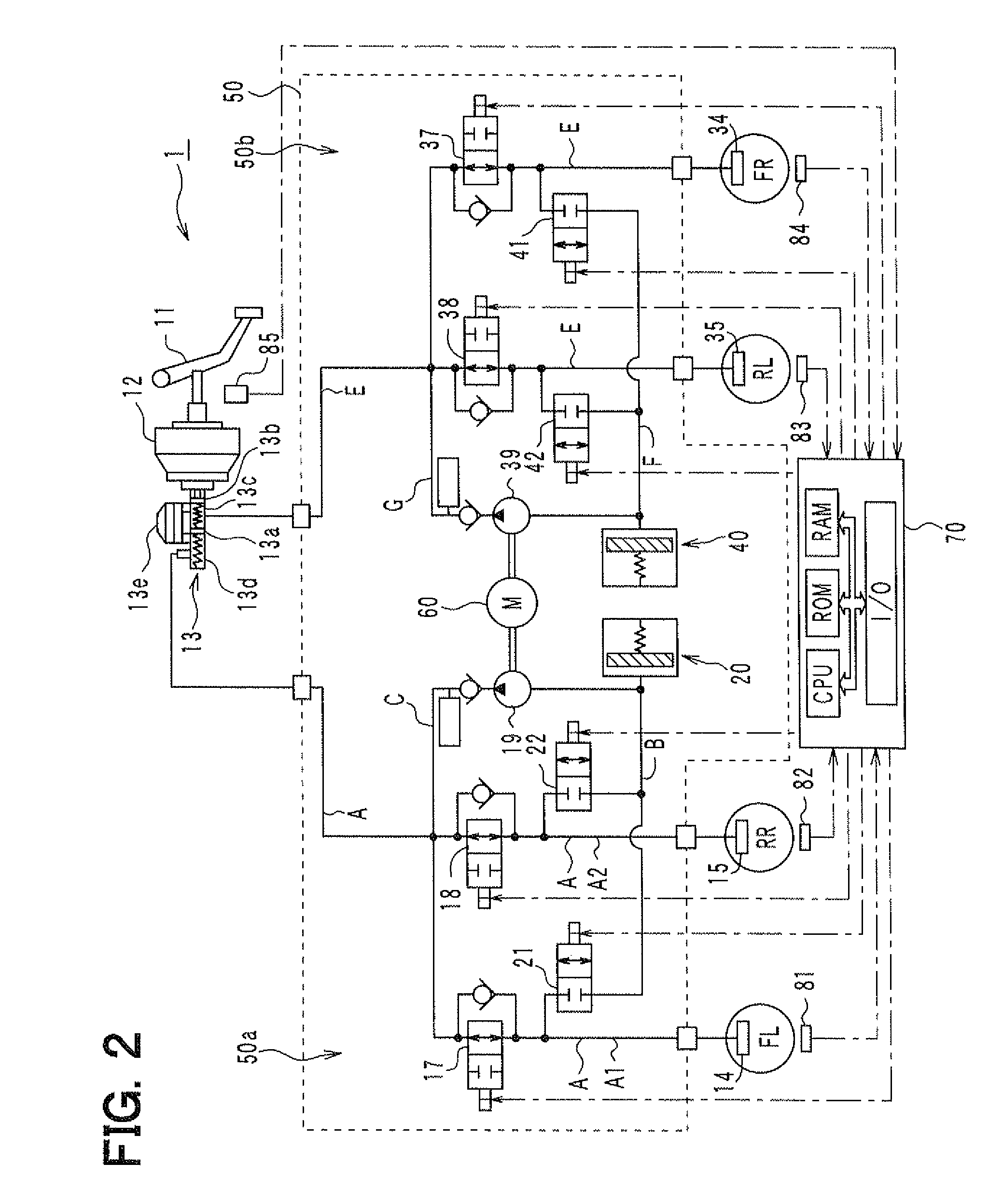
[0057]The brake control apparatus 1 according to the present embodiment will be explained. As shown in FIG. 1, the brake control apparatus 1 has a brake pedal 11, a brake booster 12, a master cylinder (M / C) 13, wheel cylinders (W / C) 14, 15, 34 and 35, and a hydraulic brake actuator 50 for controlling brake fluid pressure. The brake control apparatus 1 has a brake control ECU 70 for controlling a braking force generated by the brake control apparatus 1. More exactly, the brake control apparatus 1 has wheel speed sensors 81 to 84 respectively provided for each wheel (FL, FR, RL, RR) and outputting a detecting signal (pulse signal) depending on a wheel speed. The detecting signals from those wheel sensors 81 to 84 as well as detecting signals from other sensors (explained below) are inputted to the brake control ECU 70, so...

second embodiment

[0185]A second embodiment of the present invention will be explained. A braking operation of the second embodiment is different from that of the first embodiment. Other structure and operation are the same to those of the first embodiment. Different portions from the first embodiment will be explained.

[0186]According to the present embodiment, the braking operation will be carried out by use of the brake control apparatus 1 and an operation for EBD (Electronic Brake force Distribution) control is carried out for adjusting distribution of the braking forces between front and rear wheels. A structure of the brake control apparatus 1 is the same to that of the first embodiment. An operation to be carried out by the brake ECU 70 is different from the first embodiment. Hereinafter, the operation for the EBD control will be explained.

[0187]According to the EBD control, the braking force for the rear wheels is controlled depending on a difference of wheel speeds (a wheel speed difference) ...


PUM


Abstract

An object of the invention is to reduce an influence of deviation in pressure increasing performance, which would be caused by individual differences of pressure increase valves, so that a desired braking force may be obtained. A moderate pressure increasing operation is carried out for wheel cylinder pressure of a wheel, which is on a high μ-road, wherein a demand differential pressure for a pressure increase valve is set at a first target pressure for a first time period and then switched to a second target pressure for a second time period. The influence of the deviation may be absorbed during the moderate pressure increasing operation, so that a difference of wheel cylinder pressure between front left and front right wheels may be reduced.

Description

CROSS REFERENCE TO RELATED APPLICATION[0001]This application is based on Japanese Patent. Application No.2009-104168 filed on Apr. 22, 2009, the disclosure of which is incorporated herein by reference.FIELD OF THE INVENTION[0002]The present invention relates to a brake control apparatus for a vehicle, according to which a differential pressure between a master cylinder side and a wheel cylinder side is adjusted by controlling a pressure increase valve provided for each of wheels, so that a brake fluid pressure for each wheel cylinder (also referred to as a wheel cylinder pressure) is controlled.[0003]The present invention is preferably applied to a brake control apparatus having functions for ABS (Anti-lock Brake System) control for preventing a locked condition of the wheels during a braking operation and / or for EBD (Electronic Brake force Distribution) control for adjusting distribution of braking forces between front and rear wheels.BACKGROUND OF THE INVENTION[0004]According to a...

Claims


Application Information

Patent Timeline
IPC IPC(8): B60T8/1761B60T13/68B60T8/34G06F19/00B60T8/176B60T8/17B60T8/1764B60T8/26
CPCB60T8/1764B60T8/1766B60T13/686B60T13/662B60T8/505
Inventor SAWADA, MOTOTSUGU
Owner ADVICS CO LTD
Why Eureka
Try Eureka