Control device for three-phase brushless motor

Inactive Publication Date: 2009-01-01
MITSUBISHI ELECTRIC CORP
View PDF12 Cites 17 Cited by
  • Summary
  • Abstract
  • Description
  • Claims
  • Application Information

AI Technical Summary

Benefits of technology

[0008]This invention has for its object to propose a control device for a three-phase brushless motor, in which the deviations of the energization switchin

Problems solved by technology

In a case where errors have developed in the mounting positions of the three position sensors, positional deviations occur in the position detection signals.
Besides, in a case where errors have developed in the magnetized positions of the rotor or a position detecting rotor, positional deviations similarly occur in the position detection signals.
The positional deviations of the position detection signals afford deviations to the energization switching timings of the stator coils based on the switch circuit, they incur unnecessary rotational fr

Method used


Image

  • Control device for three-phase brushless motor
  • Control device for three-phase brushless motor
  • Control device for three-phase brushless motor

Examples


Example

Embodiment 1

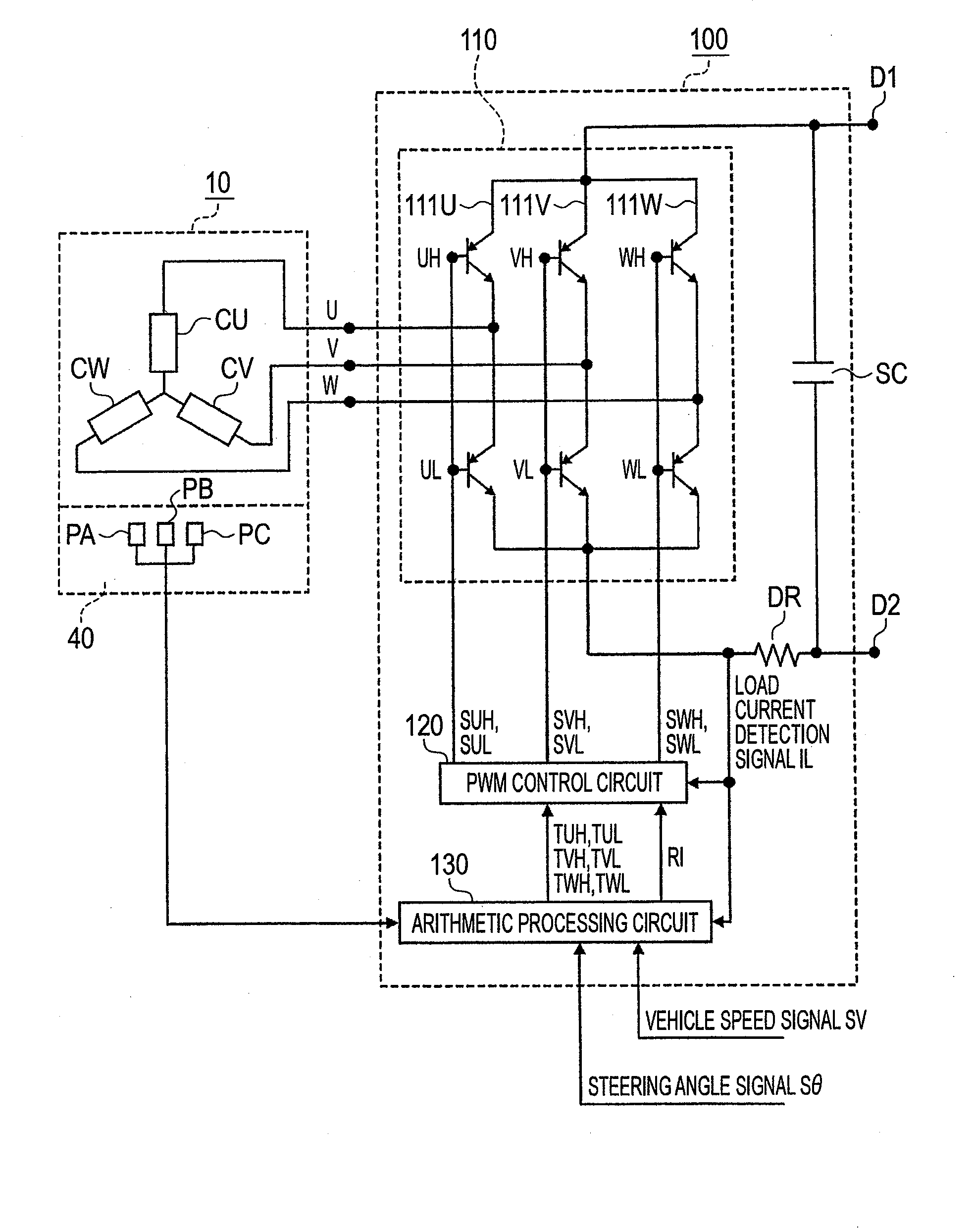
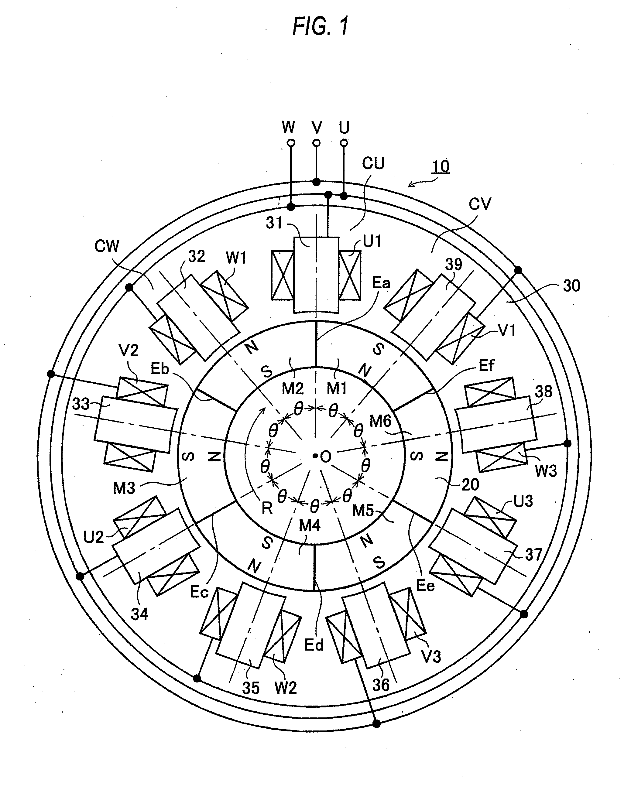
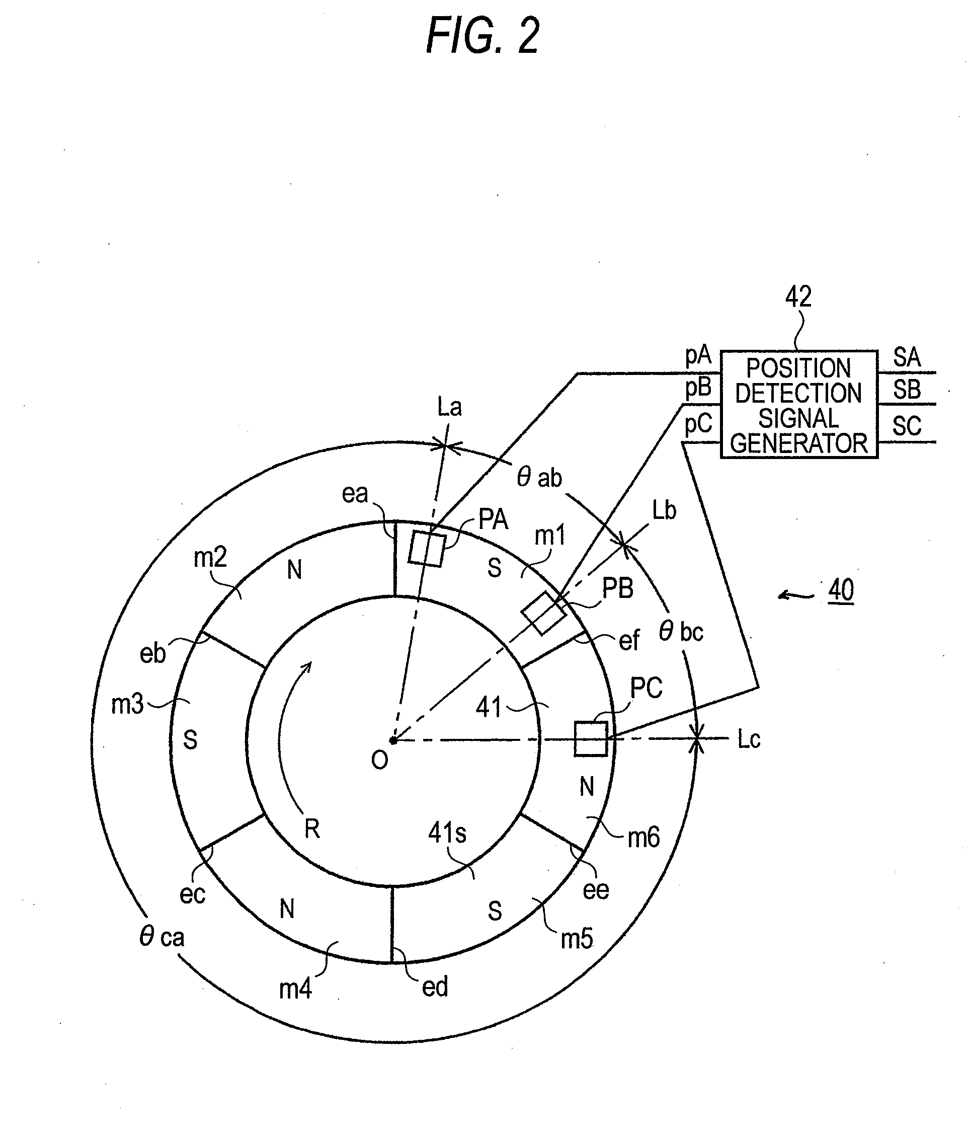
[0032]FIG. 1 is a diagram for explaining the configuration of a three-phase brushless motor in Embodiment 1 of a control apparatus for the three-phase brushless motor according to this invention. FIG. 2 is a diagram for explaining the configuration of a position detection signal generation device in the three-phase brushless motor in Embodiment 1. FIG. 3 is an electric circuit diagram showing the control apparatus for the three-phase brushless motor in Embodiment 1. FIG. 4 is a block diagram showing the internal configuration of an arithmetic processing circuit in the control apparatus for the three-phase brushless motor in Embodiment 1. FIG. 5 is a timing chart for explaining the operation of Embodiment 1.

[0033]The control apparatus for the three-phase brushless motor in Embodiment 1 includes the three-phase brushless motor 10, and a control circuit 100 therefor. The three-phase brushless motor 10 is utilized for, for example, a vehicular power steering control apparatu...

Example

Embodiment 2

[0095]Embodiment 1 has been so configured that the time-interval-calculation-mode setting means 135 gives the time interval calculation means 133 the time interval calculation mode command TQ of the section number Q=2 on the basis of the external command TO, and that the time interval calculation means 133 calculates each of the time intervals t21-t26, between the two position detection signals px and py lying at both the ends of the two continuous sections q. In Embodiment 2, the time-interval-calculation-mode setting means 135 gives the time interval calculation means 133 a time interval calculation mode command TQ of section number Q=3 on the basis of the external command TO, and the time interval calculation means 133 calculates each of time intervals t31-t36, between two position detection signals px and py lying at both the ends of three continuous sections q. The other configuration of Embodiment 2 is the same as in Embodiment 1.

[0096]FIG. 9 is a timing chart for ...

Example

Embodiment 3

[0112]In Embodiment 3 here, the time-interval-calculation-mode setting means 135 gives the time interval calculation means 133 a time interval calculation mode command TQ of section number Q=4 on the basis of the external command TO, and the time interval calculation means 133 calculates each of time intervals t41-t46, between two position detection signals px and py lying at both the ends of four continuous sections q. The other configuration of Embodiment 3 is the same as in Embodiment 1.

[0113]FIG. 10 is a timing chart for explaining the operation of Embodiment 3. Rotational positions P1-P18 on the axis of abscissas in FIG. 10 are the same as in FIG. 5, and respective signal waveforms shown at (a)-(j) in FIG. 10 are also the same as in FIG. 5. The time interval calculation means 133 successively calculates the time intervals t41-t46 appended at (a), (b) and (c) in FIG. 10. These time intervals t41-t46 will be concretely described.

[0114]First, the time intervals t41 are...


PUM


Abstract

A control apparatus for a three-phase brushless motor, in which a control circuit includes time interval calculation means (133 in FIG. 4). The time interval calculation means (133) is endowed with at least one time interval calculation mode. In the time interval calculation mode, pluralities of time intervals which correspond to an addition section obtained by adding up two or more Q continuous sections are calculated on the basis of two position detection signals which lie at both the ends of the addition section, among position detection signals successively generated. The control circuit determines pluralities of energization switching timings on the basis of the pluralities of time intervals. The control apparatus for the three-phase brushless motor can decrease the deviations of the energization switching timings attributed to the errors of the mounting positions of position sensors or to the errors of the magnetized positions of a rotor, without requiring any complicated adjustment.

Description

BACKGROUND OF THE INVENTION[0001]1. Field of the Invention[0002]This invention relates to a control device for a three-phase brushless motor.[0003]2. Description of the Related Art[0004]A three-phase brushless motor has a plurality of stator coils arranged around a rotor which is configured of permanent magnets. The number N of the stator coils is equal to the number of slots between the respectively adjacent stator coils, and it is also called the “slot number”. A switch circuit for switching energizations is connected to the N stator coils. The switch circuit switches the energizations for the respective stator coils in accordance with the rotation of the rotor. This switch circuit changes-over energization switching timings for the N stator coils, on the basis of position detection signals which a position detection signal generation device generates. The position detection signal generation device includes three position sensors, and the position detection signals are successive...

Claims


Application Information

Patent Timeline
IPC IPC(8): H02P6/16H02P6/08H02P6/06
CPCH02P6/142H02P6/15Y10S388/928H02P6/16
Inventor MIYAJIMA, MASAYASUSUZUMURA, JUNOONISHI, TOSHIYUKIOHATA, KATSUMI
Owner MITSUBISHI ELECTRIC CORP
Why Eureka
Try Eureka