
Skin Suturing Device Using Rotating Needles

a technology of rotating needles and sutures, applied in the field of medical devices, can solve the problems of time-consuming, time-consuming, and the surgeon's time-consuming to close, and achieve the effect of saving time and money

Active Publication Date: 2012-06-28
SURGIMATIX
View PDF9 Cites 98 Cited by
  • Summary
  • Abstract
  • Description
  • Claims
  • Application Information

AI Technical Summary

Benefits of technology

The patent describes a suturing device that can be used to close skin wounds. The device has two curved needles that rotate in opposite directions to create a secure and precise suture. The needles are designed to enter the dermal layers of the skin and can be easily attached to a suture thread. The device is easy to use and can help reduce the time and effort required to close skin wounds. The patent also describes a tissue suture that has a pre-insertion orientation and a post-insertion orientation, allowing for a more secure and helical suture.

Problems solved by technology

While effective, manual suturing is certainly not without its drawbacks.
For example, in the case of body contouring surgery, relatively large incisions in excess of many centimeters may be made which can often take the surgeon a very long time to close.
Not only is it time consuming, but surgeons often view the process as tedious.
Moreover, the repeated movement of the needle through the skin of the patient necessarily increases the risk to the surgeon or assistant of being exposed to a needle prick which in turn can lead to certain transmissions of diseases including but not limited to Hepatitis C and HIV.
Foremost among those drawbacks is the significant scarring associated with staples.
Moreover, staples are significantly more painful to the patient in that they need to be removed after being installed and after the incision is healed.
This can potentially avoid a significant level of pain associated with metal staple removal, but may result in significant scarring or poor wound healing in general.
This is due to: (a) less than optimal alignment associated with such absorbable staplers between the two sections of skin to be fastened; (b) poor wound holding strength which can result in areas of wound separation if there is any tension on the wound edges (tension which is not uncommon during the post-operative period) and; (c) and creation of small areas of wound separation where the thick fasteners extrude through the incision (known clinically as “spitting” of the fasteners).
Current absorbable dermal stapling technology provides less than optimal horizontal and vertical alignment.
However, the method in which the fasteners hold the wound edges in eversion results in prominent “dimpling” of the skin where the fasteners secure the skin edges, a closure appearance which can cause concern to surgeons when they try dermal staplers for wound closure.
While the '824 application attempts to position the first and second sections of skin relative to one another, the use of such an H-shaped anchor does not adequately pull the two sections close together after insertion and thus would result in longer healing times and more scarring than is acceptable.
Once it is so deployed and released, the anchor is pulled back by the opposite prong and the normal tension on the wound edges, thus resulting in slack in the anchor and a loose “seam”.
Moreover, the '824 application uses a complex system of rotating approximation arms to push the first and second sections of skin toward one another prior to insertion of the anchor.
Not only does this make the device more complicated and expensive to manufacture and prone to reliability problems, but once the approximation arms are retracted so too are the sections of skin and again the resulting closure does not ensure optimal alignment, which would lead to prominent or otherwise poor scarring.

Method used


Image

  • Skin Suturing Device Using Rotating Needles
  • Skin Suturing Device Using Rotating Needles
  • Skin Suturing Device Using Rotating Needles

Examples


Embodiment Construction

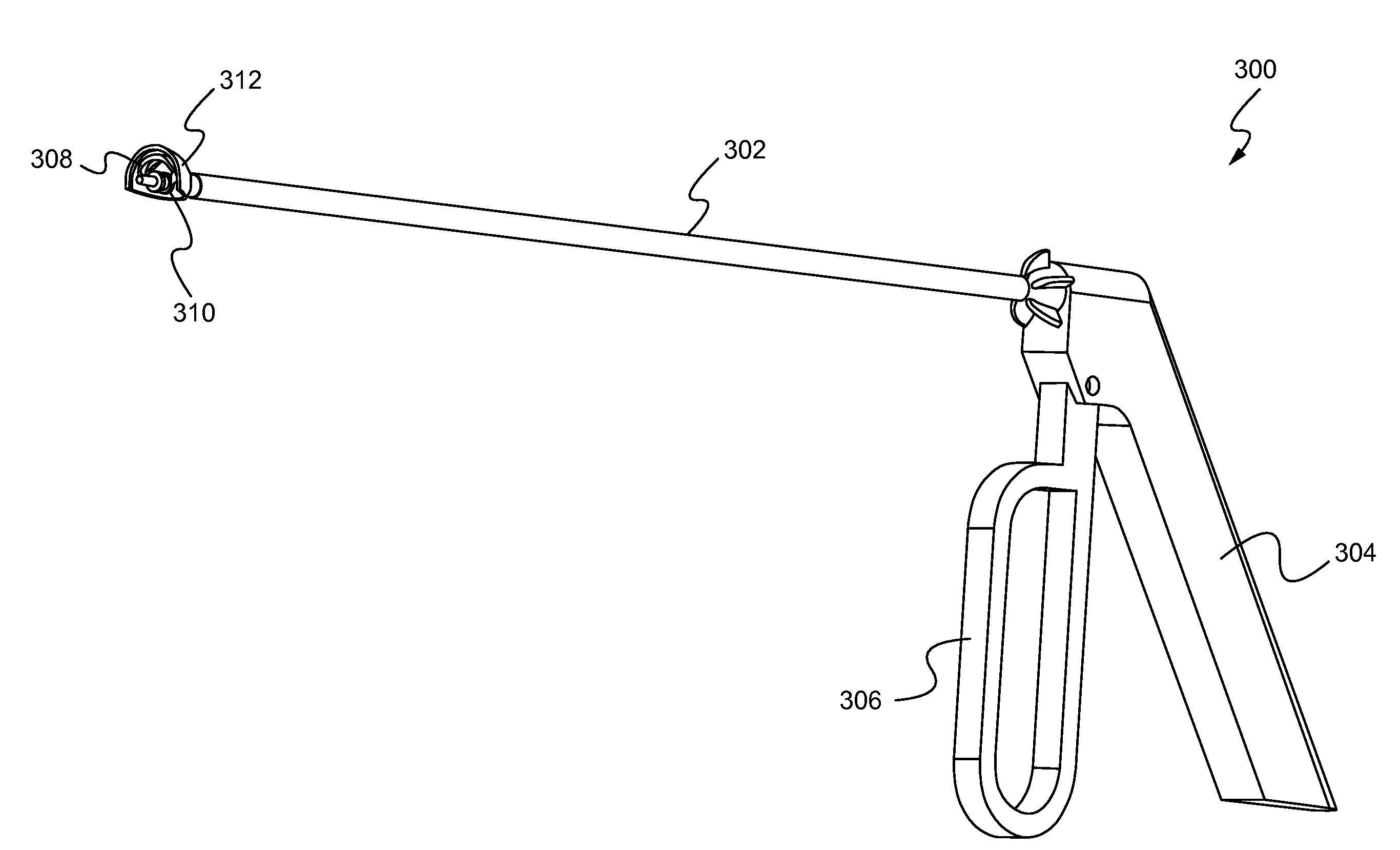
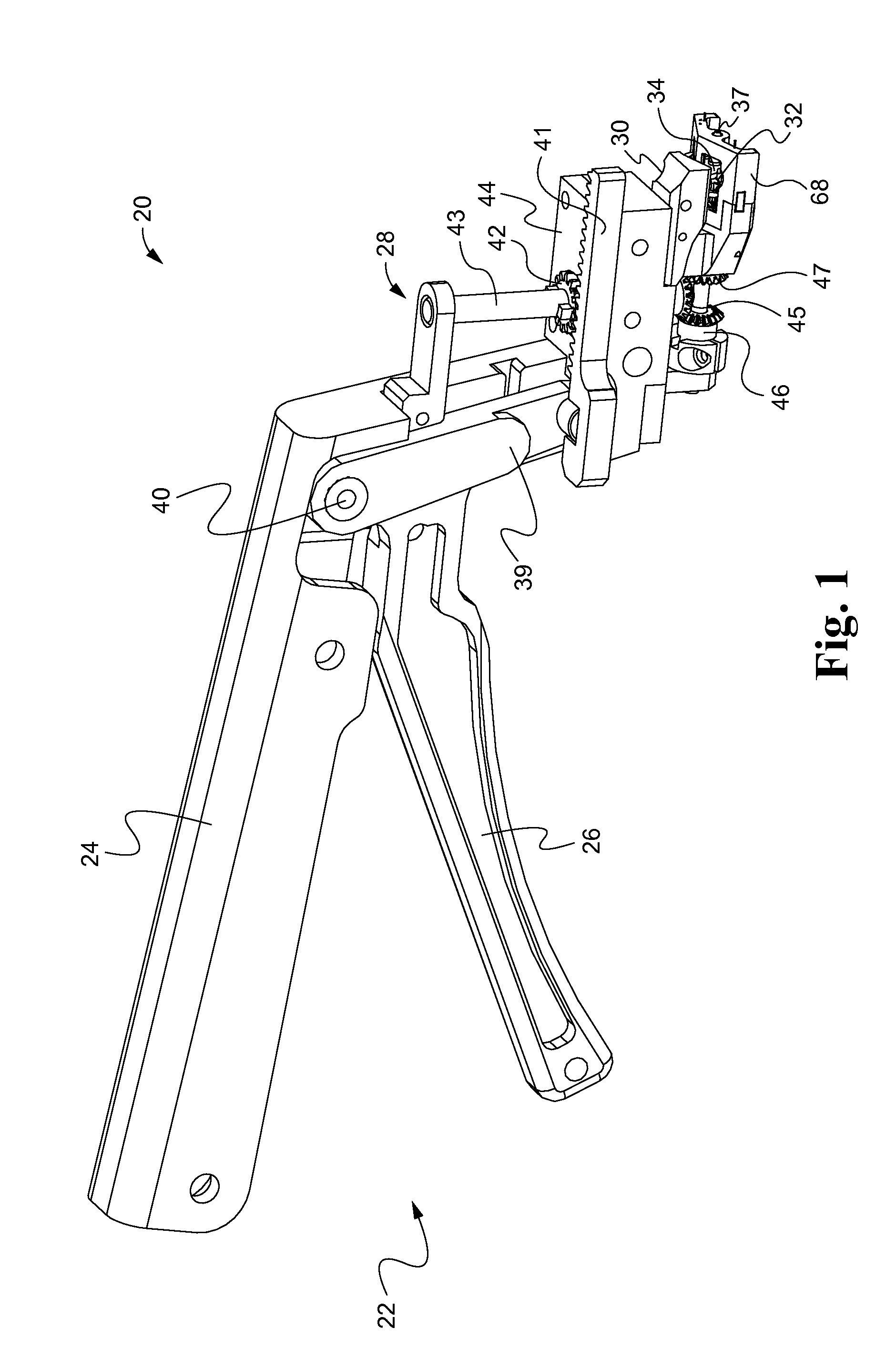
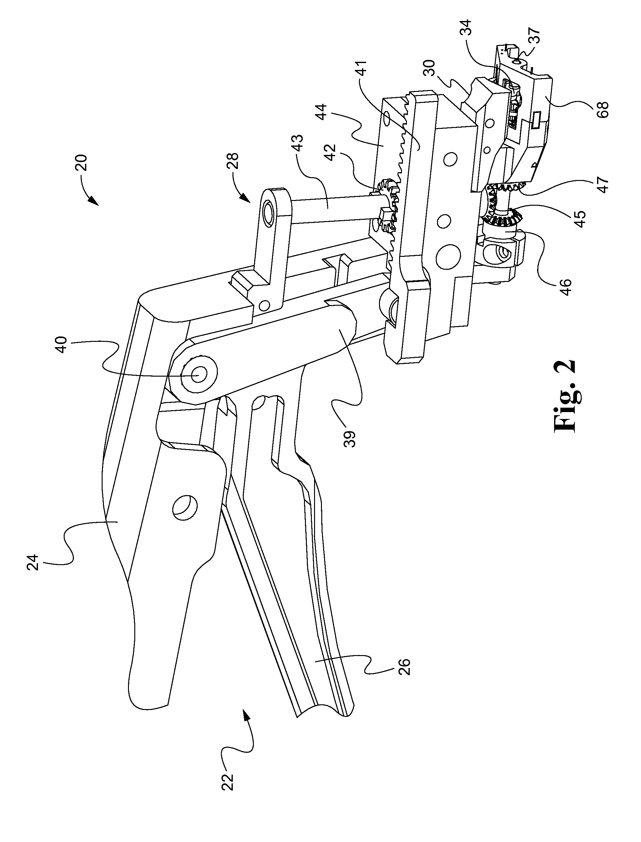
[0049]Referring now to the drawings, and with specific reference to FIG. 1, a suturing device constructed in accordance with the teachings of the present disclosure is generally referred to by reference numeral 20. The device, as will be described in further detail herein, is advantageous for surgically closing incisions, not only quickly, but with closely approximated edges and minimal scarring. Of course, the suturing device 20 can also be used to close lacerations from traumatic events such as accidents, or the like. The first embodiment of FIGS. 1-9 of the suturing tool 20 is designed to be placed under the skin sections of the skin to be sutured, and then place a suture into the dermal layers of the skin. In later described embodiments, suturing tools are described to be used against the epidermal layer of the skin, from the outer skin surface, or be used laparoscopically. Although the embodiments disclosed herein demonstrate suturing as applied to skin, it will be understood t...


PUM


Abstract

A medical device for installing sutures to close an incision in tissue or human skin is disclosed. The suturing device may provide first and second arcuate needles. Once properly positioned, the first and second arcuate needles are driven through the sub-dermal layer, or alternatively through a superficial surface, of two sections of skin to be joined. This is done in arcuate fashion and at identical and symmetrical rates of angular displacement. During the driving or retraction process of the first and second arcuate needles, a suture is positioned within both the first and second sections of skin and transformed from a planar or a multi-planar serpentine orientation to a helical orientation. The resulting suturing process is thus much faster than conventional or manual suturing and results in superior wound approximation / alignment that will lead to decreased scarring compared to prior art devices.

Description

CROSS-REFERENCE TO RELATED APPLICATION[0001]This application is based on and claims priority from U.S. Provisional Application Ser. No. 61 / 427,003, filed on Dec. 23, 2010.FIELD OF THE DISCLOSURE[0002]The present disclosure generally relates to medical devices, and more particularly relates to medical devices for suturing skin.BACKGROUND OF THE DISCLOSURE[0003]The closure of incisions or lacerations in human skin has long been a need in the medical industry. Whether the incision is the result of surgeries such as cosmetic surgery or internal organ operations, or those generated by traumatic events or accidents, surgeons are continually presented with patients needing closure of such skin openings. For example, modern studies indicate that approximately 30 million such operations are performed each year in the U.S. alone.[0004]In closing such incisions, surgeons are able to choose from a relatively limited number of options currently available. One of those options is manual suturing....

Claims


Application Information

Patent Timeline
Patent Type & Authority Applications(United States)
IPC IPC(8): A61B17/062A61B17/04
CPCA61B17/0469A61B17/0482A61B17/0483A61B17/0491A61B17/06166A61B2017/2941A61B2017/0472A61B2017/06042A61B2017/0608A61B2017/06176A61B17/29A61B17/06066A61B2017/0498
Inventor KOBYLEWSKI, GARY MICHAELCHIN, WAI NAGAIHASAN, JAFAR SYED
Owner SURGIMATIX
Learn More