
Flade discharge in 2-d exhaust nozzle

Active Publication Date: 2012-07-05
GENERAL ELECTRIC CO
View PDF2 Cites 19 Cited by
  • Summary
  • Abstract
  • Description
  • Claims
  • Application Information

AI Technical Summary

Benefits of technology

"The patent describes an aircraft gas turbine engine with a row of FLADE fan blades that are connected to a fan in the fan section. The FLADE fan blades extend across a duct and are in fluid flow communication with a two-dimensional air discharge fluid passage. The engine also includes a valve that can open and close the upstream and downstream discharge slots, which are located upstream and downstream of the nozzle discharge area. The valve can be slid aft or forward to open or close the slots. The engine can also include an afterburner and a two-dimensional exhaust nozzle. The technical effects of the patent include improved engine performance and efficiency during different modes of operation."

Problems solved by technology

Variation in the nozzle exit area is important for attaining high performance across the flight envelope, however, this is in conflict with airframe designers objectives to maintain a fixed structure for low observable and mechanical reasons.

Method used


Image

  • Flade discharge in 2-d exhaust nozzle
  • Flade discharge in 2-d exhaust nozzle
  • Flade discharge in 2-d exhaust nozzle

Examples


Embodiment Construction

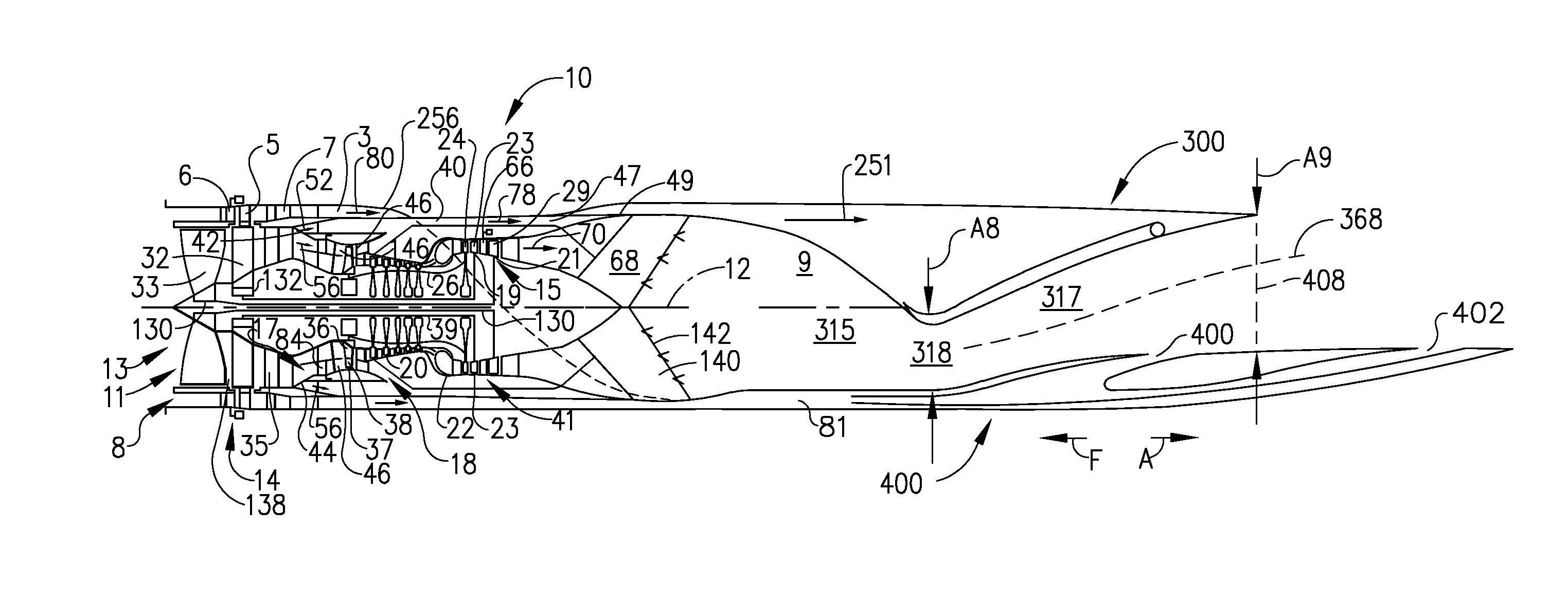
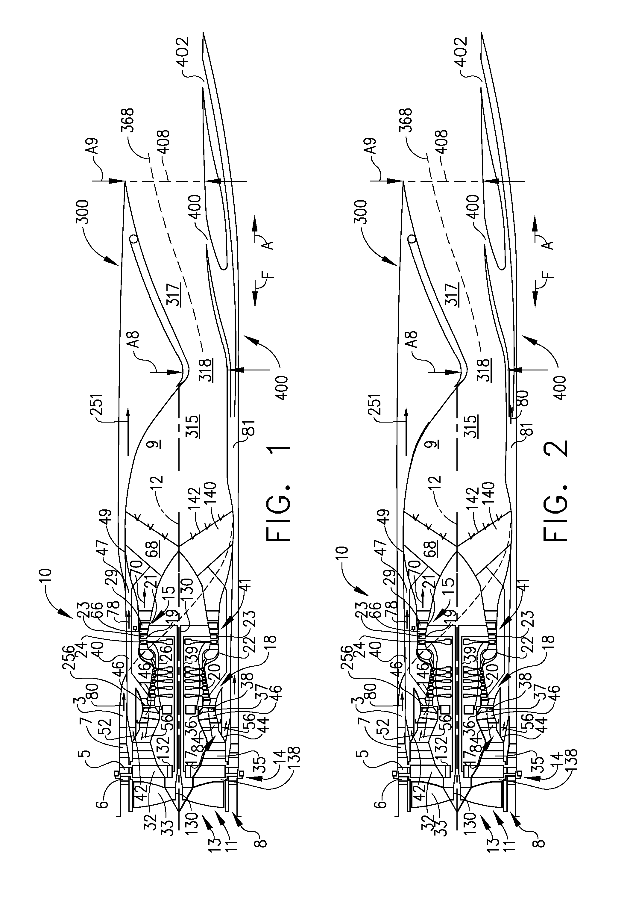
[0024]Schematically illustrated in cross-section in FIG. 1 is an exemplary aircraft “fan-on-blade” or FLADE engine 10 with a two-dimensional exhaust nozzle illustrated herein as a single expansion ramp nozzle referred to herein as a SERN 300. The engine 10 is a variable cycle engine and is described in greater detail in U.S. Pat. No. 5,404,713, entitled “Spillage Drag and Infrared Reducing Flade Engine” and U.S. Pat. No. 7,395,657, entitled “Flade Gas Turbine Engine With Fixed Geometry Inlet”, both of which are assigned to the General Electric Co., the same assignee as for this patent and both of which are incorporated herein by reference.

[0025]A FLADE engine (FLADE being an acronym for “fan on blade”) is one particular type of variable cycle engines characterized by an outer fan driven by a radially inner fan and discharging its flade air into an outer fan duct which is generally co-annular with and circumscribes an inner fan duct circumscribing the inner fan.

[0026]The FLADE fan ai...


PUM


Abstract

An aircraft gas turbine engine has a row of FLADE fan blades disposed radially outwardly of and drivingly connected to a fan in the engine's fan section. The FLADE fan blades extend across a FLADE duct circumscribing the fan section. A two dimensional air discharge passage is in fluid flow communication with the FLADE duct and with FLADE air upstream and downstream discharge slots in a divergent flap of a two dimensional exhaust nozzle. A valve fully closes the upstream slot when the downstream slot is fully opened and fully opens the upstream slot when the downstream slot is fully closed. The upstream and downstream slots may be located upstream and downstream respectfully of a nozzle discharge area in the nozzle. A sliding deck slides aft or down to open upstream slot and close downstream slot and slides forward or up to close upstream slot and open downstream slot.

Description

BACKGROUND OF THE INVENTION[0001]1. Field of the Invention[0002]This invention relates to FLADE aircraft gas turbine engines and, more particularly, to exhaust nozzles of such engines.[0003]2. Description of Related Art[0004]One particular type of variable cycle engine called a FLADE engine (FLADE being an acronym for fan on blade) is characterized by an outer fan connected to and thus driven by a radially inner fan and discharging its flade air into an outer fan duct which is generally co-annular with and circumscribes an inner fan duct circumscribing the inner fan. One such engine disclosed in U.S. Pat. No. 4,043,121, entitled “Two Spool Variable Cycle Engine”, by Thomas et al., provides a flade fan and outer fan duct within which variable guide vanes control the cycle variability by controlling the amount of air passing through the flade outer fan duct.[0005]Other high performance aircraft variable cycle gas turbine FLADE engines capable of maintaining an essentially constant inl...

Claims


Application Information

Patent Timeline
Patent Type & Authority Applications(United States)
IPC IPC(8): F02K3/06
CPCF02C9/20F02K1/08F02K1/10F02K1/82F02K7/16F02K3/075F02K3/077F02K3/10F02K3/072F02K1/06F02K1/09F02K1/30F02K3/062F02K3/065F02K3/08
Inventor LARIVIERE, ERIN LEEETTORRE, STEPHEN MICHAEL
Owner GENERAL ELECTRIC CO
Learn More