Alignment-related operation and position sensing of electronic and other locks and other objects

a technology of position sensing and alignment, applied in the direction of alarm locks, snap fasteners, instruments, etc., can solve the problems of ineffectiveness of obstruction indicators such as buzzers in many situations, lock cannot be picked, etc., and achieve the effect of reducing mechanical wear and tear and not wasting electric power

Active Publication Date: 2012-07-05
SECUREALL CORP
View PDF3 Cites 90 Cited by
  • Summary
  • Abstract
  • Description
  • Claims
  • Application Information

AI Technical Summary

Benefits of technology

[0006]An obstruction indicator such as a buzzer is ineffective in many situations, for example when the lock is installed in a public building where people may not understand the buzzer significance or may be unwilling to take time and remove the obstruction. In any case, whether or not a buzzer is appropriate, some embodiments of the invention provide an alignment system for sensing ...

Problems solved by technology

An obstruction indicator such as a buzzer is ineffective in many situations, for example when the lock is installed in a public building where people may not understand the buzzer si...

Method used


Image

  • Alignment-related operation and position sensing of electronic and other locks and other objects
  • Alignment-related operation and position sensing of electronic and other locks and other objects
  • Alignment-related operation and position sensing of electronic and other locks and other objects

Examples


Embodiment Construction

[0041]The embodiments described in this section illustrate but do not limit the invention. In particular, the invention is not limited to particular dimensions or other details except as defined by the appended claims.

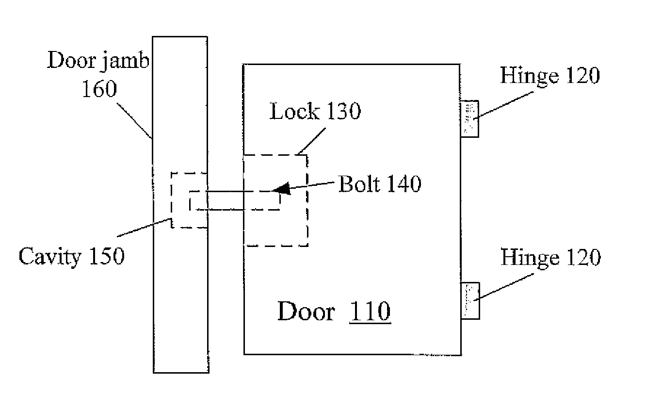
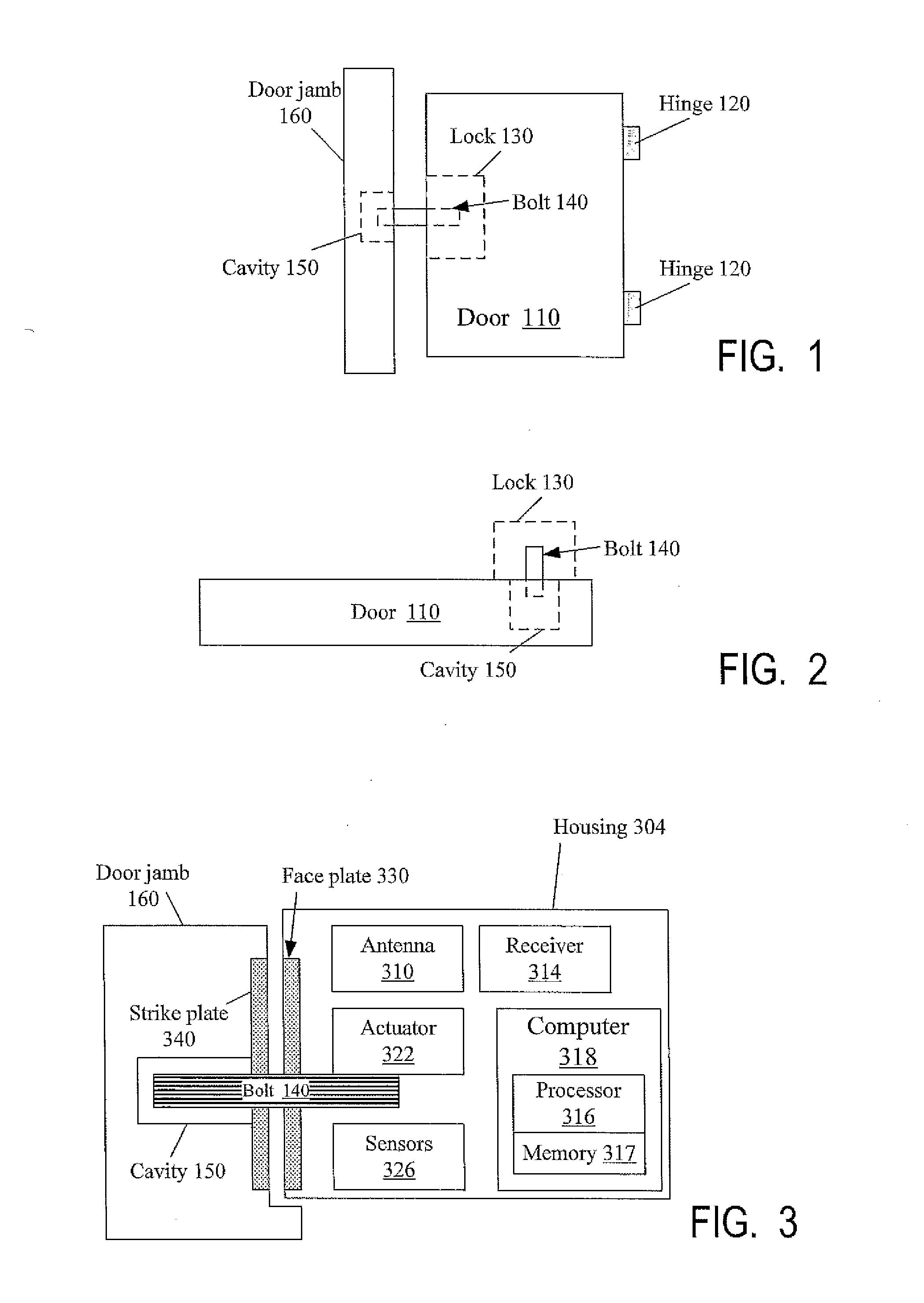
[0042]Some embodiments will now be described for a conventional door lock arrangement shown in FIG. 1. A vertical door 110 swings on hinges 120 between an open position and a closed position. When the door is closed, its left edge faces a stationary door jamb 160. A lock 130 includes a bolt (plunger) 140 which extends from the lock's housing into a cavity 150 in door jamb 160 to lock the door. To unlock the door, the bolt 140 is retracted from cavity 150.

[0043]The invention is not limited to this arrangement however. Lock 130 may be installed in the door jamb, with cavity 150 located in door 110. Lock 130 may be installed at the top or bottom of door 110, and bolt 140 can move vertically to engage a cavity in the door if the bolt is mounted on the door frame or on the ...


PUM


Abstract

A sensing system senses whether or not a lock's bolt (140), e.g. deadbolt, is aligned with a hole (150) which the bolt is to engage in the locked state. In electronic locks, the bolt is not driven into the hole until the sensing system indicates that the bolt is aligned with the hole. Another sensing system senses the position of the bolt and/or a dead-latch bar (1310). This sensing system is spaced from the bolt's end engaging the hole in order not to interfere with the alignment sensing. The two sensing systems are used to determine whether the lock is locked or unlocked. A magnet system provides alignment assistance to align the bolt with the hole before the bolt is driven into the hole. Position encoding for lock and non-lock devices, and other features and embodiments are also provided.

Description

CROSS-REFERENCE TO RELATED APPLICATIONS[0001]The present invention claims priority of U.S. provisional patent application No. 61 / 428,093, filed Dec. 29, 2010, incorporated herein by reference.BACKGROUND OF THE INVENTION[0002]The present invention relates to alignment and position sensing of locks and other objects. While the invention is applicable to different types of objects, some aspects of the invention were motivated by electronic deadbolt locks.[0003]Unlike spring bolts which are spring-biased into an extended (locked) position, a deadbolt is not biased, and has to be extended by turning a key or a knob or, in electronic operation, by an electro-mechanical actuator (e.g. motor, solenoid, etc.). When a door with a spring-bolt lock is being closed, the door jamb pushes the spring bolt into the door and the spring bolt retracts. In contrast, the deadbolt does not need to retract when pushed against the door jamb, and therefore deadbolts can be heavier and stronger to provide gre...

Claims


Application Information

Patent Timeline
IPC IPC(8): E05B47/02H01F7/02G01D5/34G01N21/25E05B47/00G01B11/00
CPCE05B2047/0069G01D5/268G01B11/272E05B2047/0068E05C1/02E05B17/22Y10T24/32E05B2045/0665E05B47/026G01N21/25G01D5/34G01B7/31G01D5/34715E05B2045/0685Y10T292/11Y10T70/7904Y10T292/096Y10T70/7113Y10T70/7057
Inventor SHARMA, ARUN KUMARCANDEE, DAVID ARTHUR
Owner SECUREALL CORP
Why Eureka
Try Eureka