Full-automatic cutting machine of numerical controlled valve
A cutting machine, fully automatic technology, applied in turning equipment, turning equipment, metal processing equipment and other directions, can solve the problems affecting the economic benefits of enterprises, processing quality restrictions, difficult to guarantee quality, etc., to achieve convenient and accurate CNC feeding, product The effect of stable quality and reduction of machine operating costs
- Summary
- Abstract
- Description
- Claims
- Application Information
AI Technical Summary
Problems solved by technology
Method used
Image
Examples
Embodiment 1
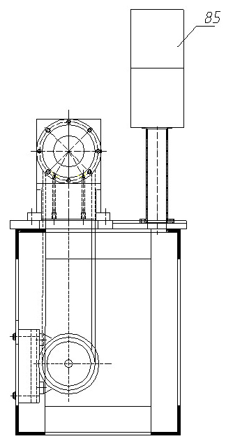
[0035] Embodiment 1: A numerically controlled valve automatic cutting machine for cutting and processing the total length of the valve according to the present invention, its structure is as follows figure 1 , 2 , including at least a positioning mechanism 81 installed on the machine bed 86, a headstock 82, a tool rest mechanism 83, a pushing mechanism 84 and a numerical control electric box 85, and the feeding mechanism 80 is installed on the bracket of the positioning mechanism and the headstock spindle On the seat; a three-phase asynchronous motor 1 is also installed in the bed of the machine tool.
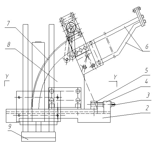
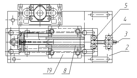
[0036] see image 3 , the feeding mechanism is composed of a feeding frame, a valve feeder and a distribution frame, the upper and lower bars 6 of the feeding frame are installed on the arc-shaped plate 8, and the arc-shaped plate and the feeding arc-shaped frame 7 are fixed on the lower bottom plate 2. The screw seat 4 and the screw seat 5 are installed on the upper and lowe...
Embodiment 2
[0041] Embodiment 2: A kind of valve L of the present invention is used 校 Numerical control type valve automatic cutting machine for fixed size grooving, see Figure 8 , the rigid ball seat rotating member installed in the middle of the positioning spindle of the cutting machine of embodiment 1 is replaced with a flexible ball seat rotating member, that is, a coupling sleeve 75, a flexible ball seat spring 76, a retaining ring 77, and a ball seat type coupling block are installed. 78. The flexible ball seat rotating member composed of steel ball 79, together with the mandrel 34 at one end of the positioning main shaft, the small spring 32 and the positioning claw 33 constitute a flexible ball seat rotary positioning head, and the piston rod of the QGB63X160 standard cylinder 27 is installed on the ball seat On the type coupling block 78, the ball seat type coupling block and the positioning main shaft are connected together to move forward and backward; at the same time, the c...
Embodiment 3
[0042] Embodiment 3: apply the valve automatic cutting machine of the present invention of embodiment 1 on the production line, its working process is:
[0043] 1. Before starting the machine, when it is necessary to change the processed valve model, adjust the position of the loading rack by adjusting the waist hole; replace the three-lobed clamp block 48 in the combined fixture; put the valve bar material to be processed into the loading rack In the upper and lower sliding rods 6, the air valve automatically moves to the front of the distribution cylinder 22 in the inclined loading rack slide rod by its own weight;
[0044] 2. Turn on the switch of the cutting machine, and turn on each motor through the numerical control electric box. Adjust the working parameters according to the needs of the processed products: by adjusting the knob, the automatic switch will be adjusted and converted into an automatic cycle;
[0045] 3. The air valves are released one by one on the feedi...
PUM
 Abstract
Description
Claims
Application Information
 - R&D
- Intellectual Property
- Life Sciences
- Materials
- Tech Scout
- Unparalleled Data Quality
- Higher Quality Content
- 60% Fewer Hallucinations
Browse by: Latest US Patents, China's latest patents, Technical Efficacy Thesaurus, Application Domain, Technology Topic, Popular Technical Reports.
© 2025 PatSnap. All rights reserved.Legal|Privacy policy|Modern Slavery Act Transparency Statement|Sitemap|About US| Contact US: help@patsnap.com


