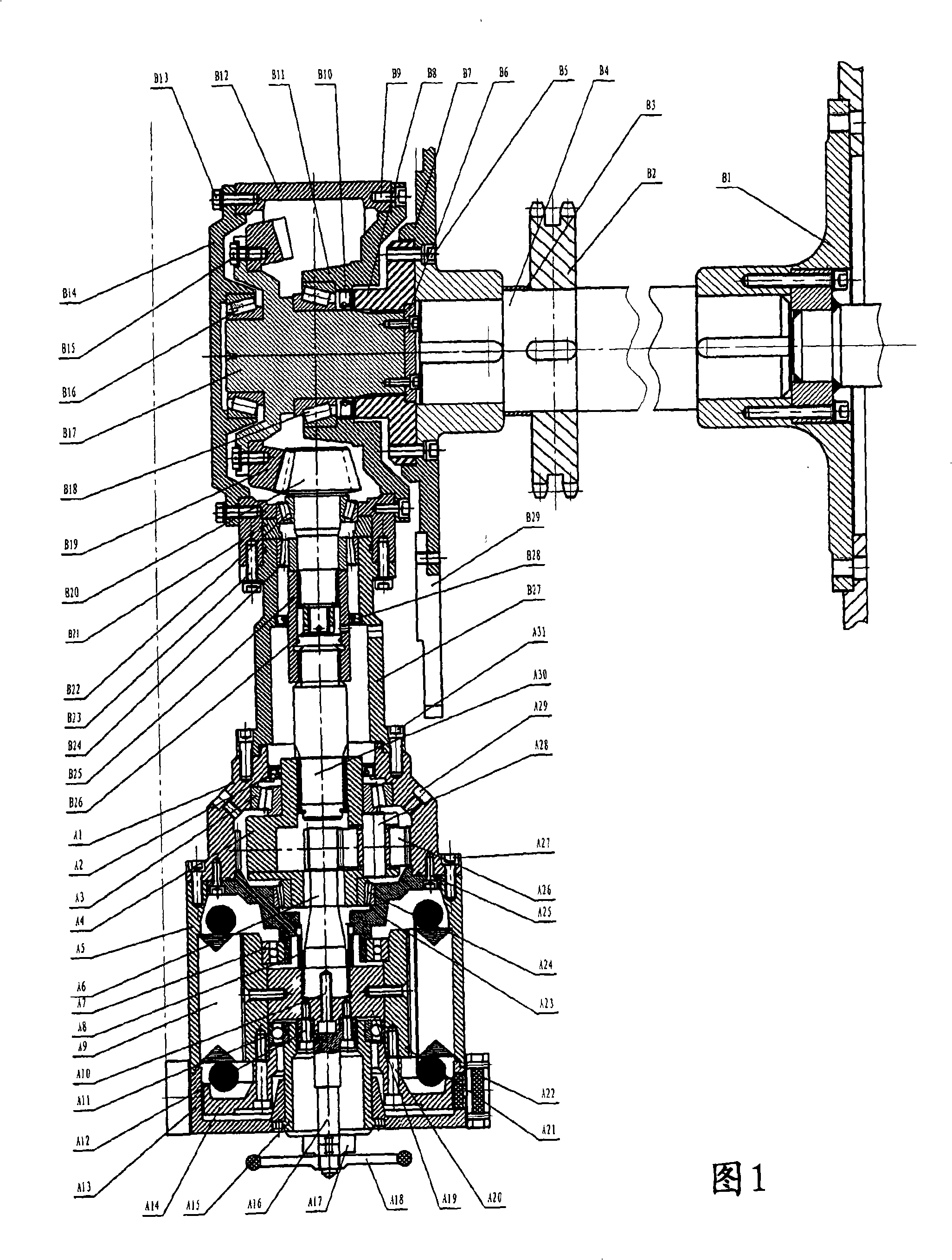
[0019] The main reference signs of the present invention are as follows
[0020] A1, ring gear housing; A2, primary lip seal; A3, front bevel gear; A4, planet carrier; A5, motor housing; A6, sun gear shaft; A7, motor front bearing; A8, mechanical seal; A9, Stator winding; A10, sun gear shaft fixing bolt; A11, motor rear bearing; A12, auxiliary shaft extension fixing bolt; A13, motor rear cover; A14, brake wheel; A15, rear hollow wheel; A16, auxiliary shaft extension; A17 , Encoder; A18, Turning handwheel; A19, Rotor triple inner spline body; A20, Brake wheel connecting bolt; A21, Permanent magnet rotor; A22, Brake; A23, Rear sealing cover; A24, Rear tapered bearing; A25, rear sealing cover fixing bolt; A26, planetary gear; A27, connecting bolt; A28, planetary gear shaft; A29, oil injection and drain bolt; A30, two-way spline connecting shaft;
[0021] B1, the right sprocket assembly; B2, the driving sprocket of the armrest belt; B3, the positioning sleeve; B4, the main drive shaft; B5, the flange connection bolt; B6, the fastening cover plate; B7, the three-way connection flange ;B8, spline flange connecting plate; B9, front cover connecting bolt; B10, spindle lip seal; B11, secondary wheel box front cover; B12, secondary gear box; B13, rear cover connecting bolt; B14, Secondary gearbox rear cover; B15, large bevel gear connecting bolt; B16, output shaft rear bearing; B17, large bevel gear shaft; B18, output shaft front bearing; B19, large bevel gear; B20, small bevel gear; B21, Bearing positioning sleeve; B22, small bevel gear front bearing; B23, bridge connecting bolt; B24, small bevel gear lip bearing; B25, two-way spline sleeve; B26, fastening bolt; B27, bridge connecting sleeve; B28, two Step lip seal; B29, step sprocket.
[0022] As shown in Figure 1, the driving device of the present invention includes a driving motor and a transmission device. The driving motor is a permanent magnet synchronous motor, and the transmission device includes a first-stage planetary gearbox and a second-stage gearbox, and the output shaft of the second-stage gearbox is coaxially connected with the main transmission shaft B4. The first-stage gearbox and the second-stage gearbox respectively adopt a first-stage planetary gear reduction mechanism and a second-stage spiral bevel gear reduction mechanism. The permanent magnet synchronous motor includes a stator winding A9 and a permanent magnet rotor A21. The permanent magnet rotor A21 is connected to the motor front bearing A7 and the motor rear bearing A11 at its front end and rear end respectively.
[0023] The first-stage planetary gear reduction mechanism includes a first-stage planetary gearbox, and the first-stage planetary gearbox includes planetary gears A24, A26, a planet carrier A4 and a sun gear shaft A6. The planet carrier is supported on the ring gear housing A1 via the front cone bearing A3. The planet carrier rear cover connected with the planet gear carrier is supported on the rear sealing cover A23 through the rear conical bearing A24. The sun gear shaft A6 of the first-stage planetary gearbox is coaxial with the central shaft of the permanent magnet synchronous motor, and the central shaft is connected to the permanent magnet rotor A21 through the rotor triple internal spline body A19.
[0024] The two-stage spiral bevel gear reduction mechanism includes a two-stage gearbox, and the output shaft of the two-stage gearbox is connected to the main transmission shaft B4. The second-stage gearbox adopts the cross meshing mode of the spiral bevel gear pair structure, and inherits the output torque of the first-stage planetary gearbox. The axis of the output shaft B17 of the secondary gearbox is perpendicular to the axis of the sun gear shaft A6. The two-stage gearbox includes a large bevel gear B19 and a small bevel gear B20 as well as a large bevel gear shaft B17 and a small bevel gear shaft. The large bevel gear shaft B17 is respectively supported on the front cover B11 of the secondary gearbox and the rear cover B14 of the secondary gearbox through the output shaft front bearing B18 and the output shaft rear bearing B16.
[0025] The output shaft end of the drive device of the present invention is equipped with a flower chain flange connection plate B8, and through the above connection screw hole and the butt joint on the three-way flange connection plate B7 installed on the shaft end of the main drive shaft B4 to carry out the same shaft connection. Complete the torque output of the escalator drive main engine, so that the main drive shaft B4 drives the step pedal sprocket B29 and the handrail drive sprocket B2 to run synchronously and smoothly on the same axis.
[0026] The primary gearbox of the present invention is collectively referred to as the "A" section and the secondary gearbox is collectively referred to as the "B" section. The connection between them and the transmission of torque between them are completed by relying on the bridge connecting sleeve B27 and the bridge connecting bolt A31 and the two-way spline shaft A30, so that the first and second gear boxes are combined into one with active Integral drivetrain components for shafts and driven shafts.
[0027] The connection between the permanent magnet synchronous motor and the planetary gear box of the present invention is through the flange screw hole on the inner ring gear housing A1 and the seam joint and positioning of the rear sealing cover A23 on the rear side of the planetary gear box, relying on the connecting bolt A27 Fastened to connect as one.
[0028] The inner ring of the motor front bearing A7 is fixed on the hollow body bearing position on the rear sealing cover A23 rear end. The inner side and the outer side of the rear sealing cover A23 respectively support and fix the outer ring of the planet carrier A4, the rear tapered bearing A25 and the inner ring of the motor rotor front bearing A7.
[0029] The rear sealing cover is a bidirectional force bearing part, the inner side bears the torque load of the planet carrier, and the rear side bears the torque load of the front end of the motor rotor A21.
[0030] The rear end of the rear sealing cover A23 is processed into a stepped hollow shaft hole, and the fixed sealing part of the mechanical seal A8 is placed in the aperture. After the sun gear shaft A6 passes through the rear seal cover A23, the rotary seal of the mechanical seal A8 is tightly sleeved on the journal. The sun gear shaft A6 is fixed on the three-connected internal spline body A19 of the rotor with a spline to form a gearbox lubricating oil sealing system.
[0031] Therefore, the gearbox is a mechanical and electrical unit with a compact structure.
[0032] The motor rear bearing A11 of the present invention is fixed on a part called the rear hollow shaft A15, and its shaft center is a hollow structure, and the motor auxiliary shaft extension A16 passes through its center. Two parts of encoder A17 and manual disc wheel A18 are installed and fixed on the secondary shaft extension.
[0033] The connection of the brake wheel A14 of the present invention and the motor rotor A21 is completed by butt joint and the fastening of the brake wheel connecting bolt A20, and its position is inside the motor rear cover A14. It forms the braking system of the escalator with the electromagnetic brake A22, and provides the moment of inertia for the motor rotor to run continuously.
[0034] The connection between the two-stage gear box of the present invention and the transmission shaft B4 is to be installed on an outer diameter spigot on the inner spline flange B9 at the large bevel gear connecting shaft B17 spline shaft end, and An inner spigot called a three-way connection flange B7 is connected coaxially and connected and fastened by flange connection bolts B5 to transmit torque.
[0035] The main engine of the present invention has a compact structure, and the gear box is flat and slender, and the primary planetary gear box and the secondary gear box can be separately installed, debugged and disassembled. The host structure is suitable for being installed in the narrow space on the end side of the escalator and the step sprocket B29 main transmission shaft.
[0036] Therefore, the escalator transmission main engine of the present invention is very suitable for the installation conditions of the truss structure of the traditional escalator.
[0037] The escalator transmission device of the present invention replaces the traditional escalator with a two-stage all-gear transmission structure, and a main transmission device composed of a worm gear reduction mechanism and a two-stage sprocket reduction mechanism. Therefore, the escalator driving device of the present invention has less mechanical wear, longer operating life and higher transmission efficiency than the traditional driving device in the transmission process.
[0038] The transmission host of the present invention can be installed on any side of the step sprocket. Moreover, it can be removed according to the needs of the installation process, because the bolt ejection hole is processed at the position of the connection hole on the three-way connection flange B7, and it can connect the three-way connection flange B7 and the inner Splined flange B8 for axial separation. The gearbox separated from the main transmission shaft B4 can be moved from the lateral position space along the radial direction of the sprocket to the platform at the position of the open sprocket port. Since the connection between the main engine and the transmission shaft is completed through the flange seam, the detachment of the main engine does not need to be moved out of the truss in the axial direction.
[0039] The driving motor configured for the driving device of the present invention is a permanent magnet frequency-variable high-speed synchronous motor, the motor efficiency is as high as 92-94%, and the power factor is close to 1. The frequency conversion speed regulation system is used for closed-loop driving, and its driving system is aimed at the change of the escalator load. The running current of the motor can be changed in a timely manner, and the running speed can also be changed according to the load conditions of people and people, so as to achieve the effect of multiple functions and energy saving of the escalator drive. The average efficiency of asynchronous motors configured in traditional escalators is only 76%, and the no-load operating current is 5-6 times higher than that of permanent magnet synchronous motors.
[0040] As shown in Fig. 2, the active reduction box of the first-stage planetary gearbox and the passive reduction box of the second-stage planetary gearbox of the present invention can also be connected separately. The gearboxes between them are installed separately, and they are connected by universal connectors, and transmit the torque of the active reduction box of the first-stage planetary gearbox to the passive reduction box of the second-stage gearbox.
[0041] It can be understood that the escalator driving AC permanent magnet synchronous motor of the present invention can also use an AC asynchronous motor of the same size, power and torque as the driving force source. The asynchronous motor can be directly input into the industrial 380-volt grid power frequency voltage power supply, and the three-phase power supply can directly drive the escalator to run.