
Unknown

a technology for starting devices and internal combustion engines, which is applied in the direction of dynamo-electric machines, ac motor stoppers, relays, etc., can solve the problems of high risk of milling between the starter element and the starter ring gear of the internal combustion engin

Inactive Publication Date: 2009-10-29
VALEO EQUIP ELECTRIC MOTEUR
View PDF6 Cites 16 Cited by
  • Summary
  • Abstract
  • Description
  • Claims
  • Application Information

AI Technical Summary

Benefits of technology

[0010]The aim of the invention is especially to solve the aforementioned drawback in a simple manner.
[0015]Thanks to the invention, the first and second electrical contact elements may be easily positioned, if so required, in a single casing, thereby avoiding having to have two contractor casings as described especially in patent application FR 2 881 479.
[0025]In one embodiment of the invention, the contractor comprises a fixed core, and an elastic return element, especially a spring, is interposed between the second contact element and the movable support of the first electrical contact element so as to make it possible, at least when the first contact element is activated and before activation of the second contact element, to apply the second electrical contact element against the fixed core of the contractor.
[0032]The invention makes it possible in particular to reduce the peak torque while the starter element is in position, tooth against tooth, on the ring gear, and thus to eliminate the risk of milling.
[0033]The invention may also prevent any reopening by return of the movable core that may occur in the case of a tooth-against-tooth position at the moment of conjunction (in which case a voltage drop due to the peak current of the electric motor and a short-circuiting of a pull-in winding of this contractor may induce a force insufficient for the movable core to undergo magnetic sticking).
[0034]In the first phase, the peak current is limited in the electric motor, thereby reducing the electrical wear of the brushes present in the electric motor. By limiting the peak torque it is possible to reduce the mechanical wear of the pinion against the ring gear.

Problems solved by technology

However, the higher the peak torque, the higher the risk of milling between a starter element of the starter and the starter ring gear of the internal combustion engine.

Method used


Image

  • Unknown
  • Unknown
  • Unknown

Examples


Embodiment Construction

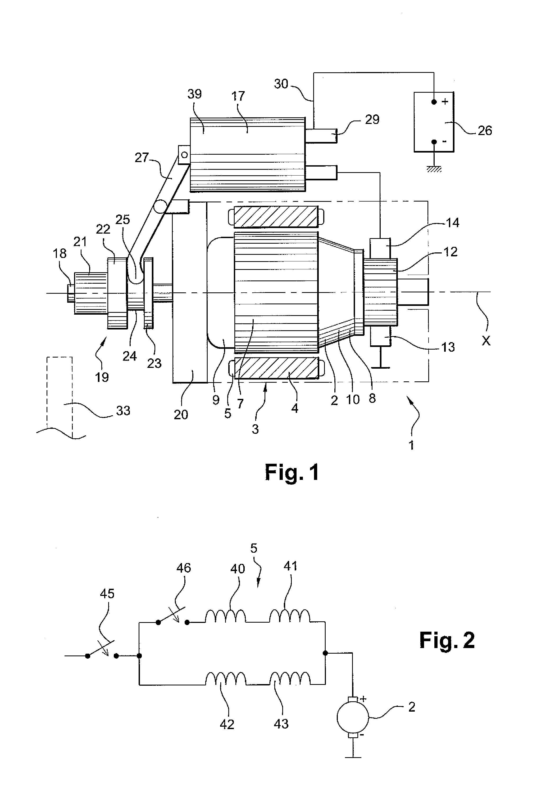
[0073]FIG. 1 shows a starting device 1 for the internal combustion engine of a motor vehicle.

[0074]This device comprises, on the one hand, a rotor 2, also called an armature, which can rotate about an axis X and, on the other hand, a stator 3, also called an inductor, around the rotor 2.

[0075]This stator 3 comprises a yoke to which one or more pole pieces 4 for positioning an inductor coil 5 are fixed.

[0076]The rotor 2 has a rotor body 7 and an armature winding 8 wound in notches of the rotor body 7.

[0077]The armature winding 8 forms, on either side of the rotor body 7, a front bundle 9 and a rear bundle 10.

[0078]To the rear, the rotor 2 is provided with a commutator 12 comprising a plurality of contact pieces electrically connected to the conducting elements, which are formed in the example in question by wires, of the armature winding 8.

[0079]A group of brushes 13 and 14 is provided for supplying power to the armature winding 8, one of the brushes 13 being connected to the earth o...


PUM


Abstract

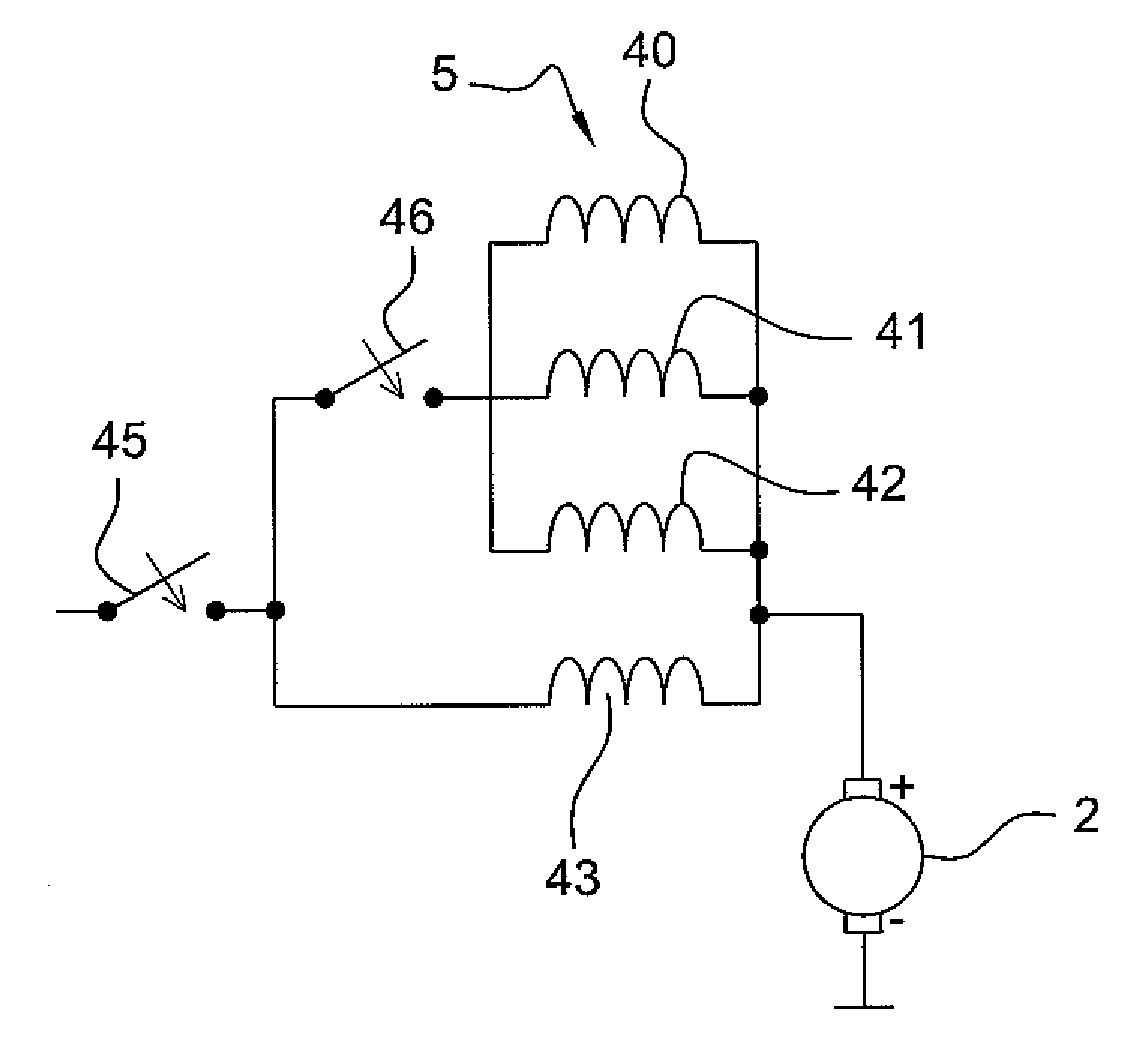
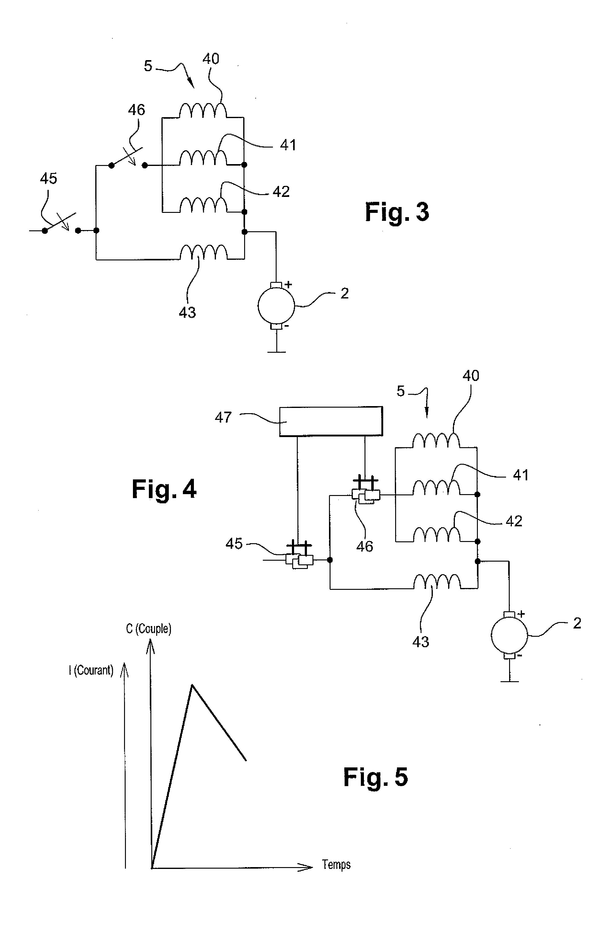
A starting device for an internal combustion engine, especially that of a motor vehicle, comprises:a stator, or inductor, comprising an inductor coil (5), said inductor coil comprising at least first (43), second (41) and third (42) windings that are all electrically connected in parallel;a rotor associated with said stator and having a longitudinal axis;a starter element that can be rotated by the rotor; anda contractor designed to supply power, in a prerotation first phase, only to the first winding (43) of the inductor coil and, in a full-speed second phase, following the first phase, to the first, second and third windings (41, 42) of the inductor coil.

Description

[0001]This application claims foreign priority benefit and right under 35 U.S.C. §119 based on French Patent application no. FR 0852529 filed Apr. 15, 2008, which is hereby incorporated by reference in its entirety.BACKGROUND OF THE INVENTION[0002]1. Field of the Invention[0003]The invention relates in particular to a starting device for an internal combustion engine, especially that of a motor vehicle.[0004]2. Description of Related Art[0005]Patent FR 2 174 421 teaches an electromagnetic contractor for an electrical motor-vehicle starter. This contractor comprises a movable part consisting of a solenoid plunger, fastened to which is a rod bearing at one of its ends a slidably mounted contact plate. This plate initially bears, especially through the action of springs, on contacts of an electrical circuit that includes a coil resistor so that, in a first starting phase, the starter rotates at low speed. In a second starting phase, this same contact plate closes an electrical circuit,...

Claims


Application Information

Patent Timeline
IPC IPC(8): H02P1/18H02K23/64
CPCF02N11/0851F02N11/0859F02N11/087F02N15/043H01H51/065F02N2011/0874F02N2300/102F02N2300/104F02N15/067F02N2300/106
Inventor LABBE, NICOLASPLAIDEAU, STEPHANEPARVERY, YANNICK
Owner VALEO EQUIP ELECTRIC MOTEUR
Learn More