Integration of a surface heat-exchanger with regulated air flow in an airplane engine

a heat exchanger and air flow technology, applied in the field of surface heat exchangers, can solve the problems of sfc, aerodynamic disruption in flow, and increase in specific fuel consumption,

Inactive Publication Date: 2012-07-05
TECHSPACE AERO
View PDF10 Cites 58 Cited by
  • Summary
  • Abstract
  • Description
  • Claims
  • Application Information

AI Technical Summary

Problems solved by technology

These are fairly heavy exchangers that have the drawback of disrupting the air flow and therefore penalizing the global output (increase in specific fuel consumption, SFC).
In fact, for brick-type exchangers, the air is supplied by a system of ducts that cause increased drag or by a bleed system of the engine air flow that causes an aerodynamic disruption in the flow.
These surface exchangers are intrinsically lighter and less intrusive, but they are not provided with regulation means, unlike brick-type exchangers.
Furthermore, although they are less intrusive, their integration into the turbomachine nevertheless poses the following problems:increased susceptibility to impacts and more particularly FOD (foreign object damage) if they are positioned in a zone exposed to the flow or centrifugation by the fan;limited heat exchange when the airplane is stopped if external zones are used;disruption of the flow, less than that of bricks but constant, with SFC impact (potential interaction with other elements in the flow such as the OGVs (Outlet Guide Vanes), and acoustic (potential interaction with the pulses of the fan).
This surface exchanger also has the drawback that it is provided with no means for regulating the cooling airflow as a function of the usage conditions of the airplane (flight or ground).
Currently, the stagnation points (nacelle and separator nose) are deiced pneumatically by air bleed at the engine or electrically, which requires mechanical sampling causing losses of propulsive output in each case.

Method used


Image

  • Integration of a surface heat-exchanger with regulated air flow in an airplane engine
  • Integration of a surface heat-exchanger with regulated air flow in an airplane engine
  • Integration of a surface heat-exchanger with regulated air flow in an airplane engine

Examples


Embodiment Construction

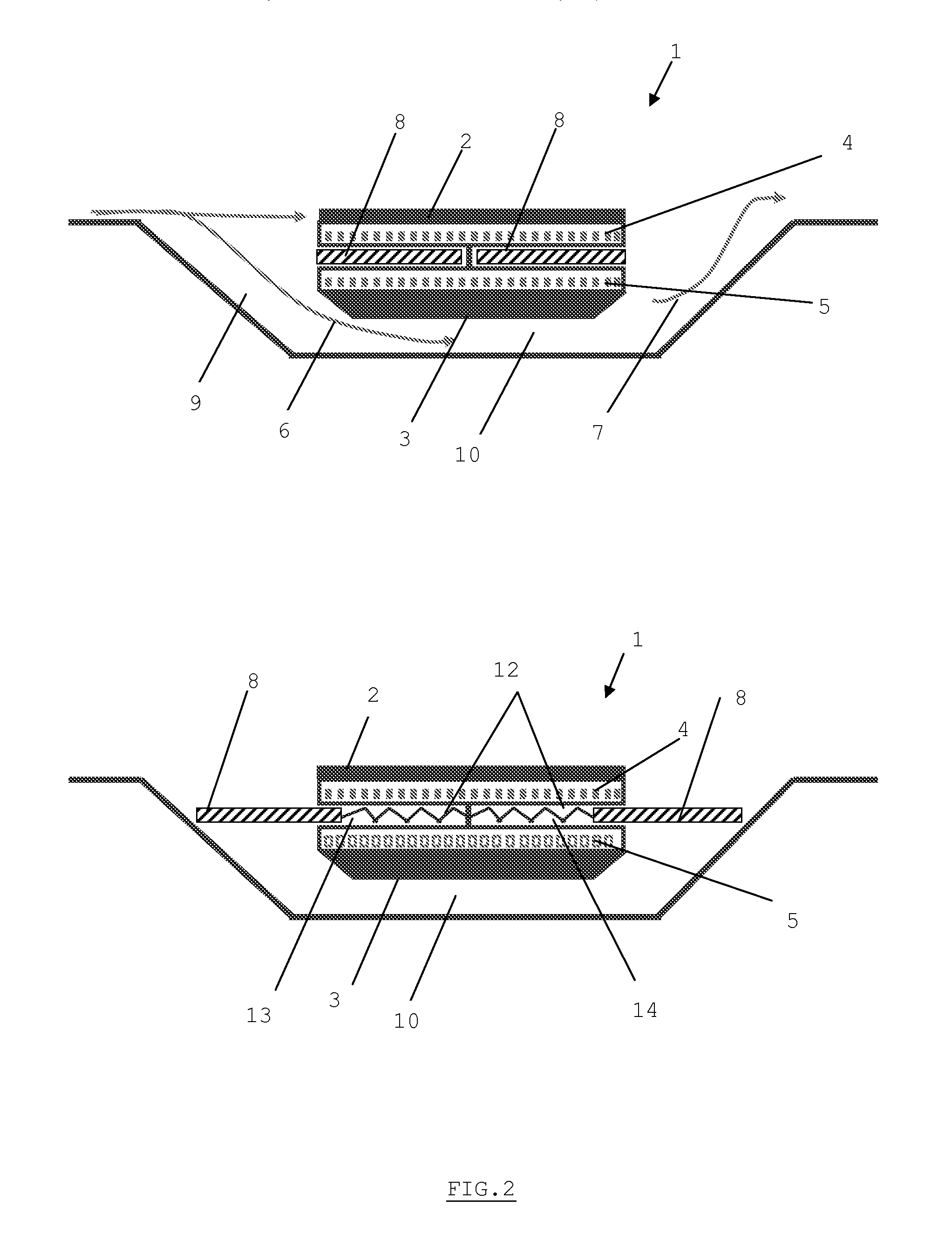
[0054]The surface exchanger as in the invention is illustrated below for embodiments where the exchanger comprises two oil circuits. The present invention also extends to other embodiments where the exchanger comprises only one oil circuit.

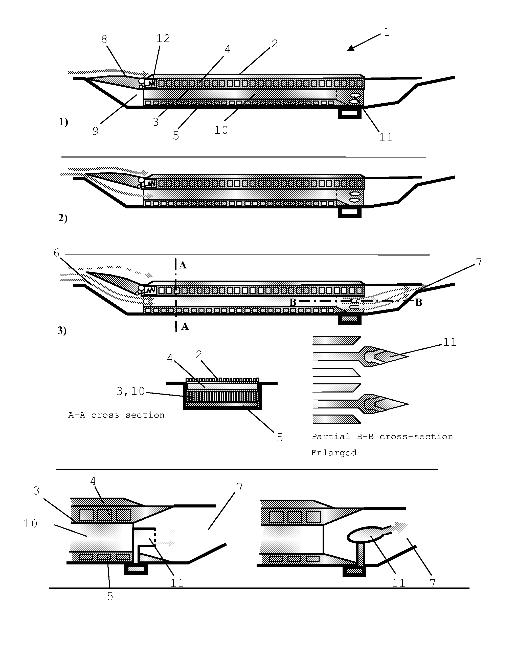
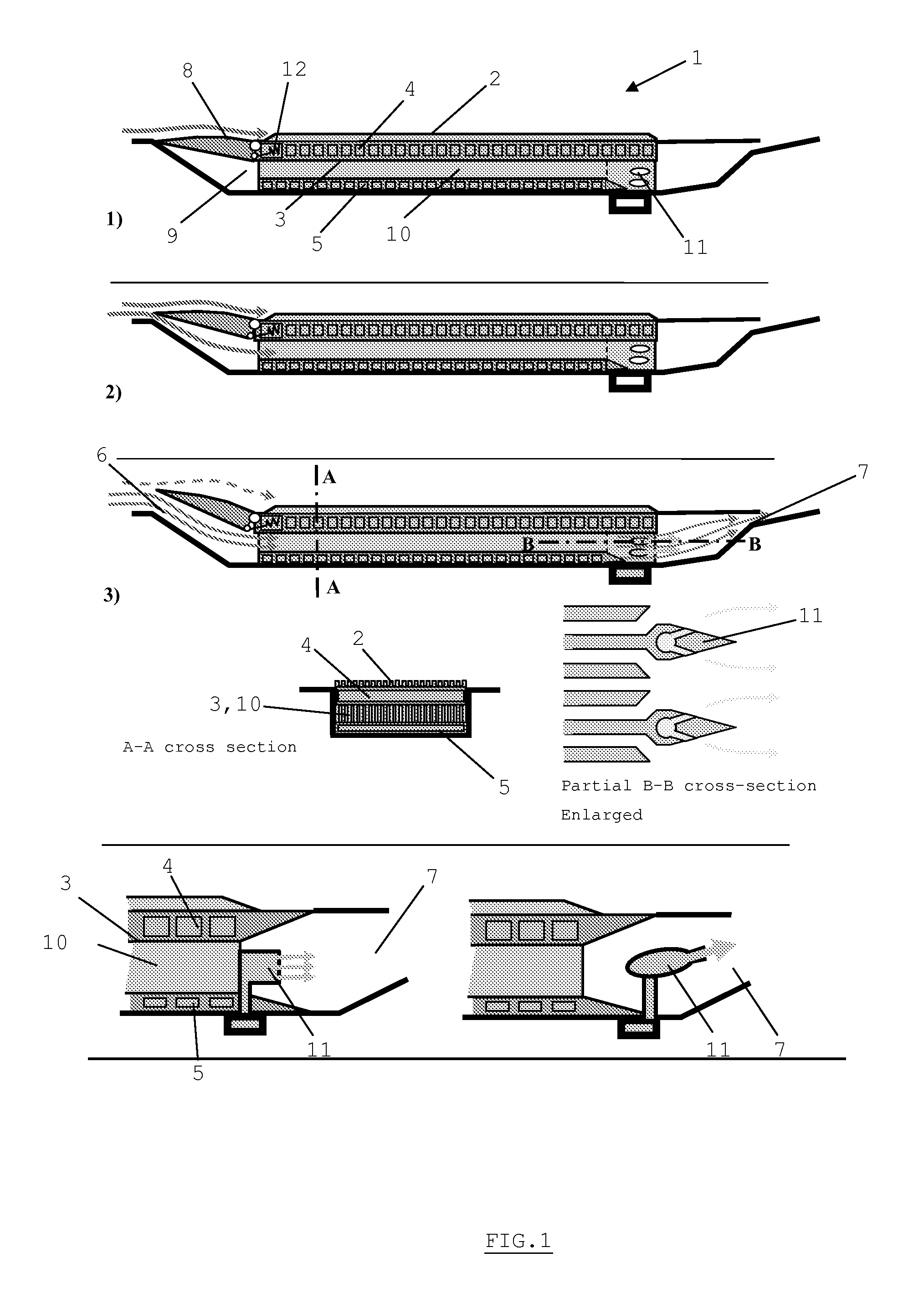
[0055]FIG. 1 illustrates a dual-path surface air-cooled oil cooler as in a first embodiment of the invention where the covering means open according to a rotational motion.

[0056]The exchanger 1 comprises a first 2 and a second exchange surfaces provided with fins. It also comprises a first 4 and a second 5 oil circuits and is provided with an air inlet 6 and outlet 7. The inlet 6 comprises covering means 8 such as a duct. The second exchange surface 3 and the second oil circuit 5 are positioned inside a cavity 9, while the first surface 2 is located outside the cavity 9. In the illustrated example, the duct opens toward the outside of the cavity and then forms a duct favoring the air inlet under its inner surface. Alternatively (not shown), the du...


PUM


Abstract

The present invention relates to a surface air-cooled oil cooler (1) in an airplane engine comprising at least one first oil circuit (4) and at least a first (2) and a second (3) exchange surface positioned on either side of the first oil circuit (4) and each able to be swept by an air flow, said second exchange surface (3) being positioned in the cavity (9) provided with an air inlet (6) and an air outlet (7), said inlet (6) and / or said outlet (7) comprising covering means (8) that allow to regulate the air supply on the second exchange surface (3).

Description

CROSS-REFERENCE TO RELATED PATENT APPLICATIONS[0001]This patent application claims the benefit of European Patent Application No. 10197456.6, filed Dec. 31, 2010, the entire teachings and disclosure of which are incorporated herein by reference thereto.FIELD OF THE INVENTION[0002]The present invention relates to a heat-exchanger in aeronautics. It more particularly relates to a surface heat-exchanger whose heat transfers can be modulated depending on the usage phases of the airplane on the ground and during flight, respectively.[0003]It also relates to a surface heat-exchanger provided with means for deicing part of the airplane.[0004]The present invention also relates to an airplane engine comprising such a heat-exchanger.STATE OF THE ART[0005]In a turbomachine, different members and pieces of equipment (bearing enclosures, gearboxes, electrical machines, etc.) must be lubricated and / or cooled, the generated heat generally being transported by oil systems and evacuated by fuel-cool...

Claims


Application Information

Patent Timeline
Patent Type & Authority Applications(United States)
IPC IPC(8): B60H1/32
CPCF01D25/02F01D25/08F01D25/12F02C7/047Y02T50/675F02K1/827F02K3/06Y02T50/672F02C7/14F28D1/0233F28D2021/0021F28F27/02Y02T50/60
Inventor RAIMARCKERS, NICOLASBORBOUSE, CÉDRICCORNET, ALBERTBAJUSZ, DENIS
Owner TECHSPACE AERO
Why Eureka
Try Eureka