

Cleaning implement with mist generating system
a technology of cleaning implements and mist, which is applied in the field of vacuum cleaners, can solve the problems of polluting the atmosphere, agitating the surface to be cleaned, and disturbing the dust and debris trapped on carpet fibers,
- Summary
- Abstract
- Description
- Claims
- Application Information
AI Technical Summary
Problems solved by technology
Method used
Image

Examples
first embodiment
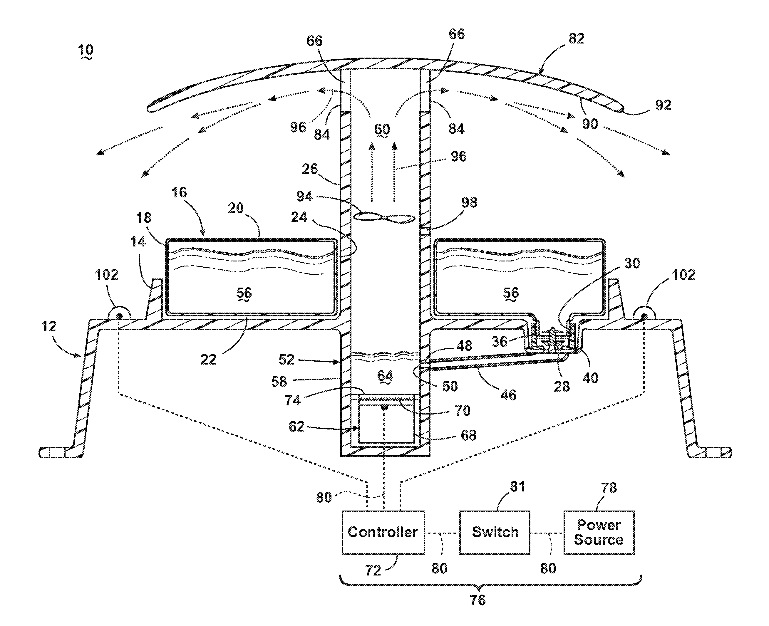
[0016]FIG. 1 is a schematic view of a modular mist generating system 10 according to the invention. The mist generating system 10 comprises a housing 12 with a mounting feature such as a recessed pocket 14 formed in a top wall thereof for selectively receiving a refillable liquid supply tank 16. The tank 16 can be molded out of transparent thermoplastic material and comprises a generally circular shape with a peripheral sidewall 18 and an enclosed top wall 20 and bottom wall 22. The tank 16 can further comprise a cylindrical opening 24 at the center thereof that is configured to surround a raised cylindrical rib 26 protruding upwardly from the center of the pocket 14.
[0017]A valve mechanism 28 for controlling the flow of liquid from the tank 16 can be provided and is selectively received within an outlet defined by a threaded neck 30 on the bottom wall 22 of the tank 16 and retained thereon by a retention cap 36. The pocket 14 can comprise a valve seat 40 that couples with the valve...
second embodiment
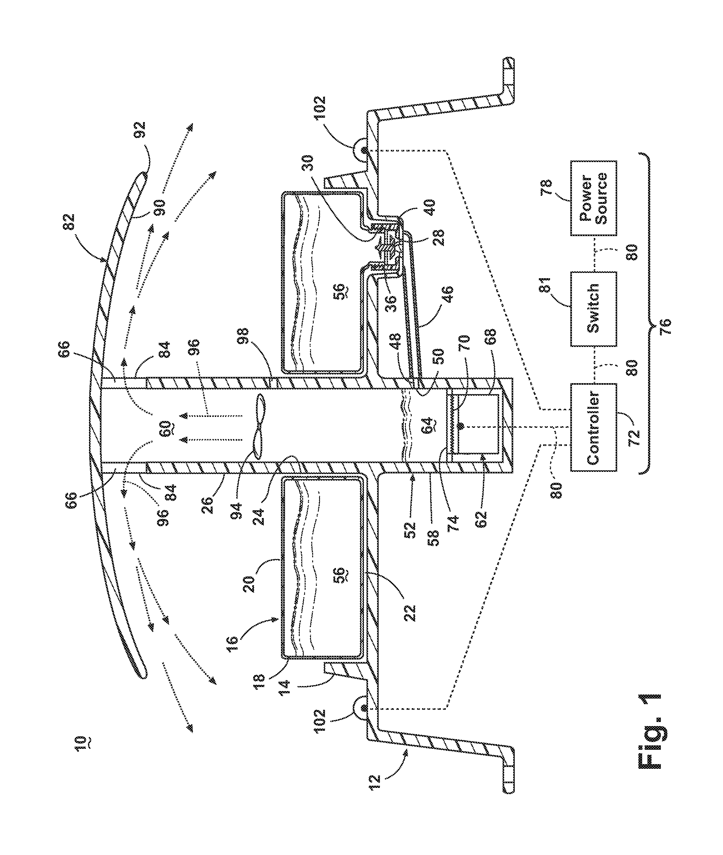
[0029]FIG. 2 shows a modular mist generating system 200 according to the invention where like features are indicated with the same reference numeral symbol. The mist generating system 200 is substantially identical to the mist generating system 10 shown in FIG. 1, except that the valve seat 40 is fluidly connected to a pump 202 and a downstream atomizing nozzle 204 that are fluidly connected by tubing 206 that is sealingly secured therebetween. The pump 202 can comprise a conventional centrifugal or solenoid design as is commonly known in the art.
[0030]The atomizing nozzle 204 comprises an elongate, cylindrical, piezoelectric transducer probe 208, a liquid inlet 210 and a nozzle outlet 212 that is fluidly connected to the liquid inlet 210 via a hollow chamber 214 extending along a longitudinal axis. The inlet 210 is fluidly connected to the pump 202 via the tubing 206. A liquid flow path is thus formed along the hollow chamber 214 of the nozzle 204, from the inlet 210 to the nozzle ...
third embodiment
[0037]FIG. 3 is a schematic view of a modular mist generating system 300 according to the invention where like features are indicated with the same reference numerals. The mist generating system 300 is similar to the mist generating system 200 shown in FIG. 2, except that a filter 304 is positioned in-line between the pump 202 and an atomizing nozzle 306. Flexible tubing segments 206 are sealingly connected between the aforementioned components to form a liquid flow path, which includes the filter 304, therethrough. Furthermore, an atomizing nozzle 306 is employed in place of atomizing nozzle 204, and can comprise a low pressure misting nozzle adapted to distribute an atomized liquid mist for suppressing dust, deodorizing a cleaning surface, or applying an atomized composition to a surface to be cleaned. The nozzle 306 can be fixed in an upward orientation relative to the housing as shown, or alternatively, the nozzle position can be adjustable relative to the housing, or it can be ...
PUM
| Property | Measurement | Unit |
|---|---|---|
| diameter | aaaaa | aaaaa |
| diameters | aaaaa | aaaaa |
| frequency | aaaaa | aaaaa |
Abstract
Description
Claims
Application Information