
Systems, Methods, and Apparatus for Lifting Brushes of an Induction Motor

a technology of induction motor and brush, which is applied in the field of induction motor, can solve the problems of inefficient brush contact with slip rings after start-up to achieve short circuit between slip rings, and the occurrence of carbon dust in the motor

Inactive Publication Date: 2012-07-05
GENERAL ELECTRIC CO
View PDF0 Cites 27 Cited by
  • Summary
  • Abstract
  • Description
  • Claims
  • Application Information

AI Technical Summary

Problems solved by technology

However, constantly maintaining brush contact with the slip rings after start-up to achieve the short circuit between the slip rings is inefficient because of the brush wear caused by a friction between the rings and brushes.
Additionally, since most brushes are carbon based, carbon dust typically accumulates in the motor from the brush wear.

Method used


Image

  • Systems, Methods, and Apparatus for Lifting Brushes of an Induction Motor
  • Systems, Methods, and Apparatus for Lifting Brushes of an Induction Motor
  • Systems, Methods, and Apparatus for Lifting Brushes of an Induction Motor

Examples


Embodiment Construction

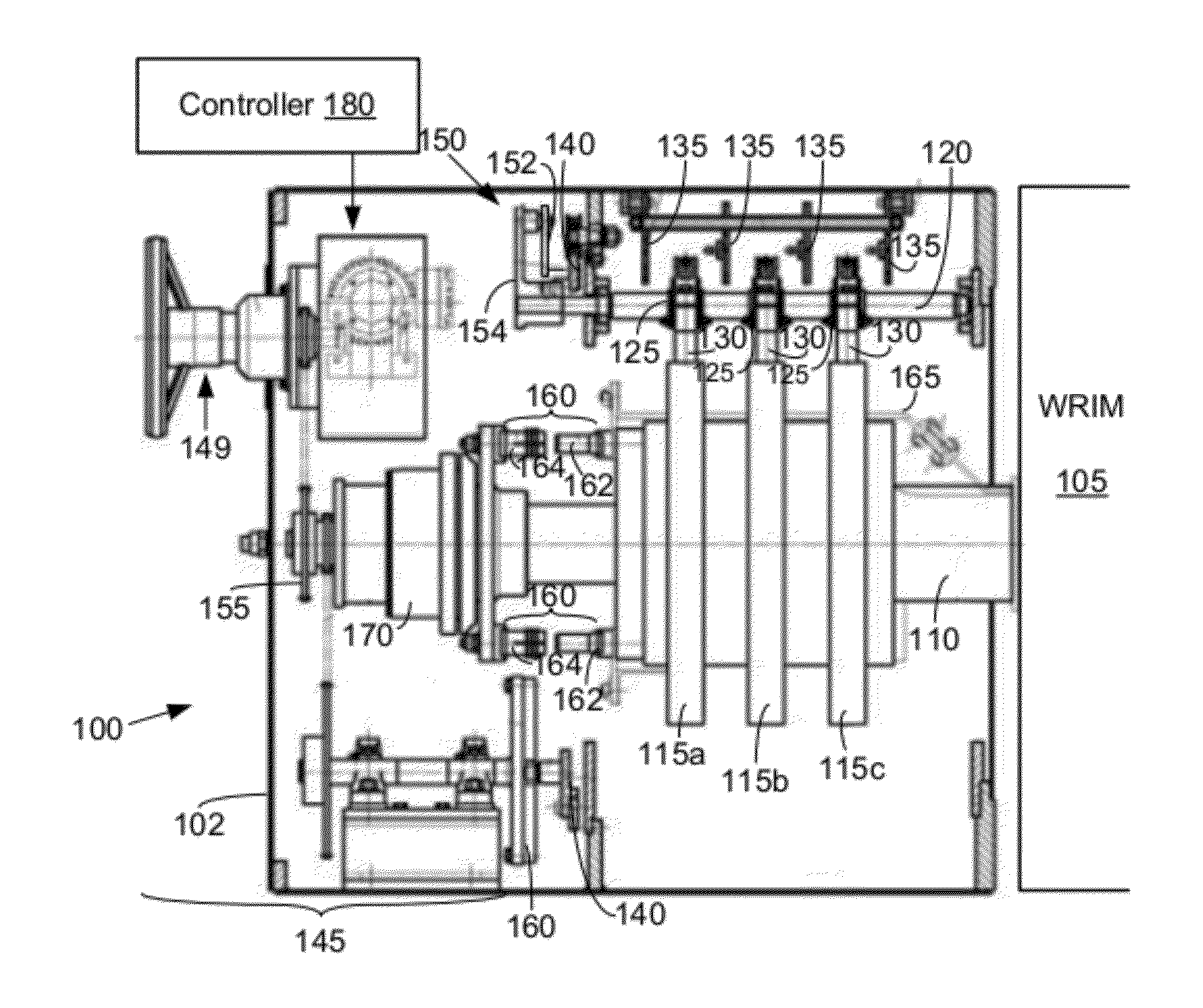
[0018]Illustrative embodiments of the invention now will be described more fully hereinafter with reference to the accompanying drawings, in which some, but not all, embodiments of the invention are shown. Indeed, the invention may be embodied in many different forms and should not be construed as limited to the embodiments set forth herein; rather, these embodiments are provided so that this disclosure will satisfy applicable legal requirements. Like numbers refer to like elements throughout.

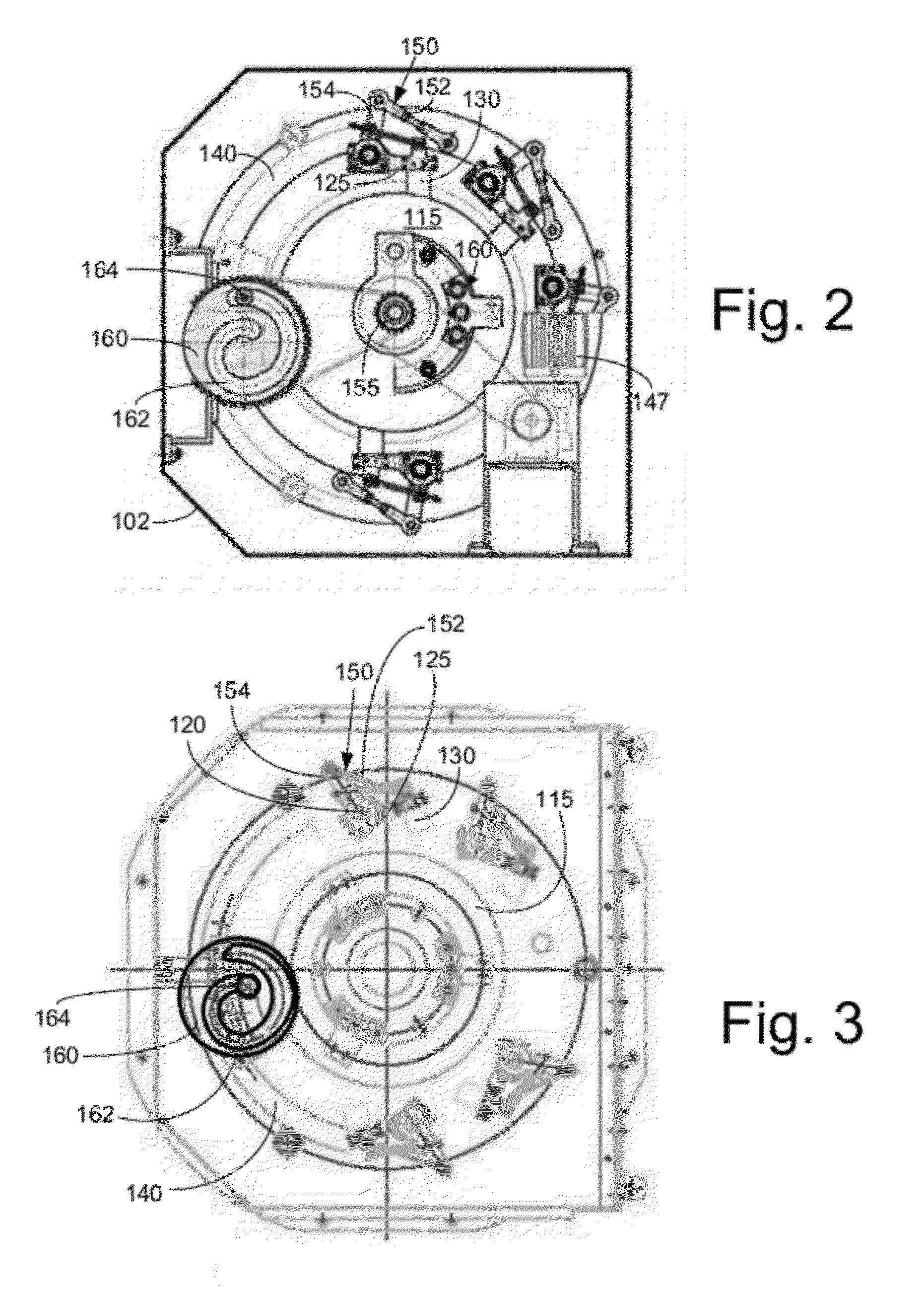
[0019]Embodiments of the systems and methods described herein provide systems, methods, and apparatus for lifting brushes and / or for shorting slip rings of a WRIM after the WRIM achieves a predetermined speed. By lifting the brushes from the slip rings and achieving an electrical short circuit between the slip rings according to these methods and systems, unnecessary wear on the brushes and rings can be avoided. According to one embodiment, the multiple brushes are positioned at locations aroun...


PUM


Abstract

Systems, methods, and apparatus associated for lifting brushes and shorting slip rings are provided. One embodiment may include an actuating mechanism in operable communication with multiple brushes and a plurality of electrical contacts. Each of the brushes may be adapted for selective contact with a respective slip ring of an induction motor. The electrical contacts may be in electrical communication with respective terminals of rotor windings of the induction motor. When the actuating mechanism is actuated, at least a portion of the electrical contacts create electrical shorts between at least a portion of the slip rings and the rotor windings of the induction motor. When the actuating mechanism is actuated, at least a portion of the brushes are lifted from contacting the plurality of slip rings.

Description

FIELD OF THE INVENTION[0001]Embodiments of the invention relate generally to induction motors, and more specifically relate to systems, methods, and apparatus for lifting brushes of an induction motor.BACKGROUND OF THE INVENTION[0002]Typically, to initially rotate the rotor of a wound rotor induction motor (“WRIM”), a high resistance is inserted into a rotor circuit to produce torque and limit current. As the angular speed of the rotor increases, the resistance is decreased. Typically, the external rotor resistance circuit is electrically connected to the rotor winding via slip rings (also referred to as “collector rings”) and brushes, the brushes applying current to the slip rings to initially energize and rotate the rotor. As the speed approaches rated values, the rotor windings are shorted so that a sufficient magnetic field can be induced into the rotor windings from the stator winding to produce the required torque. However, constantly maintaining brush contact with the slip ri...

Claims


Application Information

Patent Timeline
Patent Type & Authority Applications(United States)
IPC IPC(8): H01R39/42
CPCH01R39/42H02K23/18H02K5/148H02K13/10
Inventor TOLEDO, THIAGO AROUCAKAWASAKI, NELSONDARBHA, RADHAKRISHNA
Owner GENERAL ELECTRIC CO
Learn More