Camera support device

a technology for supporting devices and cameras, applied in the field of camera support devices, can solve the problems of existing devices, too complex for small-scale use, and inconvenient use for small-scale devices

Inactive Publication Date: 2012-07-05
EADS CONSTRS AERONAUTICAS
View PDF5 Cites 3 Cited by
  • Summary
  • Abstract
  • Description
  • Claims
  • Application Information

AI Technical Summary

Benefits of technology

[0013]With the support device according to the invention the camera contained inside it may perform a recording in any direction of the available field of vision without the need for remote control and allows a fixed field of vision to be maintained and a comparison of the different photograms taken by the camera, while allowing different focusing or lenses for different tests. Thus, the device according to the invention allows adjustment of the lens of the camera in the desired direction for each test and may be installed on any outer surface of the aircraft by adapting a support element of said device to the front outer surface of the aircraft on which it is arranged.
[0014]Moreover, the above device allows precise adjustment of the camera in order to compensate for existing deformations between the different surfaces of the aircraft where the camera is installed together with the support device, and the object in question, since, owing to these deformations, the targeted object may remain outside of the field of vision of the camera or result in the need for additional adjustments. These adjustments, owing to the design of the support device which will be described more clearly below, may be performed without having to modify either the external fairing protecting the camera or the supports on which the camera is arranged. Thus, the support device according to the invention comprises a housing element containing internally the camera, so that the housing element and the camera are able to rotate together in order to orient and position said camera. Since the housing element is situated inside the external aerodynamic fairing which protects the camera, the main advantage offered by this configuration of the support device according to the invention is that the form of the external assembly is not modified even when the camera is adjusted, since the housing element rotates (together with the camera) inside the said external fairing which remains unvaried.
[0017]a protection element, arranged between the camera and the housing element, said element protecting the camera from any possible damage which might occur when mounting the camera on the housing element;
[0020]an external aerodynamic element, intended to protect externally the entire assembly of the support device together with the viewing camera and being oriented so as to reduce the aerodynamic forces of the assembly and specifically designed for each surface on which the viewing camera is to be arranged;

Problems solved by technology

The problems posed by the solutions mentioned is that, although they are effective for large-size and heavy cameras, they represent systems which are not suitable for use in small-size cameras, such as those which are customarily used nowadays.
Thus, the devices mentioned in the prior art documents are designed to support large-size cameras which are generally controlled remotely: these existing devices are designed for different kinds of remote operation and are too complex for them to be used in the case which concerns us here, i.e. principally aimed at measuring deformations of aerofoils during flight of an aircraft using a small-size camera which must be kept in a permanently fixed position which moreover may vary between aircraft flights.
The problem of this kind of solution is that it does not have sufficient flexibility to cater for a wide range of possible orientations of the camera suitable for different conditions which may arise during different flight tests.
Generally speaking, the problems of the solutions represented by camera support devices such as those described consist, on the one hand, in the major difficulties encountered when adjusting the arrangement of the camera for each test which is to be performed in the aircraft.
Furthermore, these known solutions pose the problem that they must undergo major structural modifications when they are to be installed on different aircraft or on different surfaces within the same aircraft.

Method used


Image

  • Camera support device
  • Camera support device
  • Camera support device

Examples


Embodiment Construction

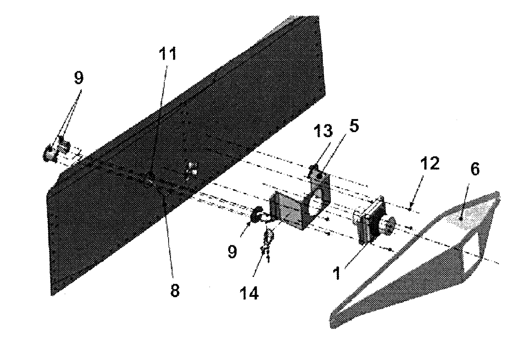
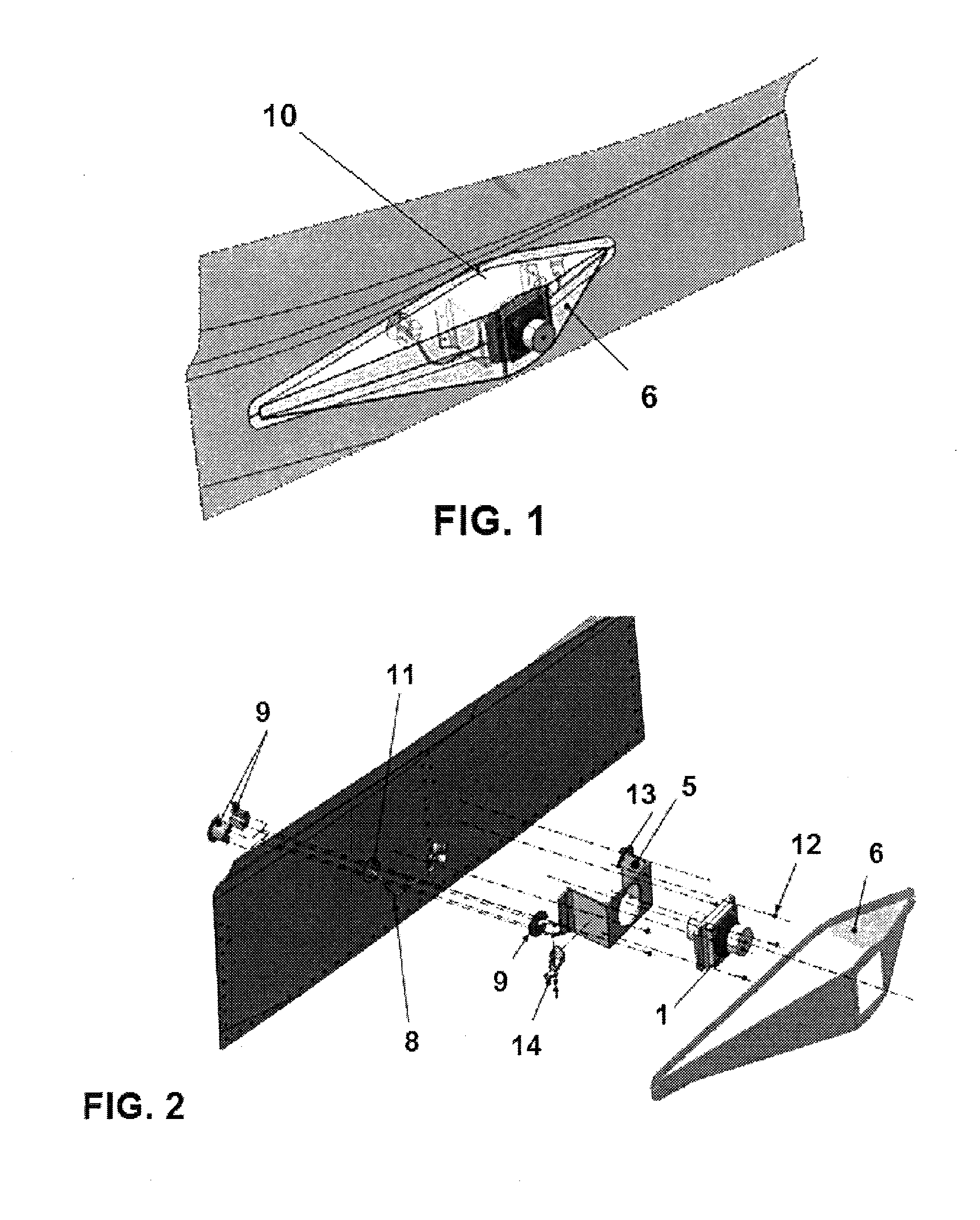
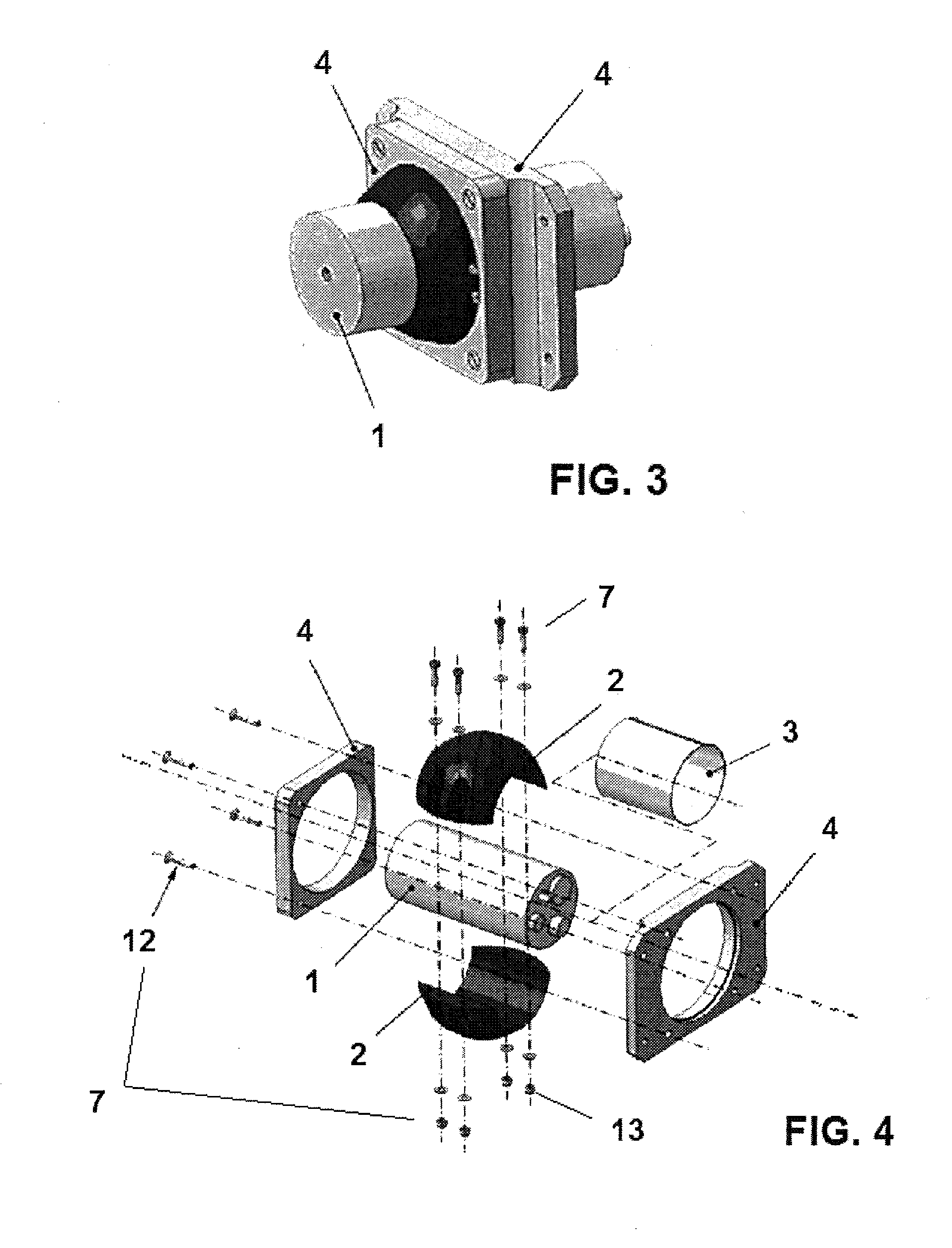
[0028]The invention thus illustrates a support device 10 for a camera 1, in particular a camera 1 for viewing flight tests of an aircraft. The support device 10 according to the invention comprises:[0029]a housing element 2, which comprises preferably externally semi-spherical parts, in particular in the form of two semi-spheres, which house internally the camera 1 (see FIG. 4), said housing element 2 reproducing internally the shape of the camera 1 so that the latter is fixed to said housing element 2, such that the camera 1 and the housing element 2 rotate together relative to the support means 4 with three degrees of freedom;[0030]a protection element 3, in particular a seal made of rubber or similar elastic material, arranged between the camera 1 and the housing element 2 and intended to reduce the damage which the camera 1 might suffer as a result of the housing element 2 when the camera 1 is mounted on the said element 2, preventing moreover the camera 1 from being damaged dur...


PUM


Abstract

Support device (10) for a camera (1) situated on the outer surface of an aircraft, which comprises a housing element (2) which houses internally the camera (1) and an external aerodynamic element (6) which covers externally the device (10), said device comprising support means (4) and adjusting elements (12) such that, when the adjusting elements (12) are tightened, the support means (4) keep the housing element (2) and the camera (1) in a fixed position and with a fixed orientation so that pictures may be taken by the camera (1) and, when the adjusting elements (12) are not tightened, the housing element (2) and the camera (1) may be rotated with three degrees of freedom relative to the support means (4).

Description

FIELD OF THE INVENTION[0001]The present invention relates to a support device for a camera, in particular a camera for viewing aircraft flight tests.PRIOR ART[0002]During the in-flight tests of an aircraft it is often required to record different aspects of a given test, whether it be the aerodynamic behaviour of movable surfaces of the aircraft, or other aspects, visual verification of which cannot be performed by the aircraft crew because of physical obstacles, or flight characteristics which must be recorded to obtain civil or military certification of the aircraft.[0003]Traditionally cameras have been installed for this purpose on the inside or of outside an aircraft so that the abovementioned aspects or characteristics may be suitably recorded. In the case of cameras which are to be installed on the outside of the aircraft, the support devices for carrying said cameras must be made to a high specification on account of the aerodynamic loads which they must withstand; at the sam...

Claims


Application Information

Patent Timeline
Patent Type & Authority Applications(United States)
IPC IPC(8): H04N5/225
CPCB64D47/08G03B17/561G03B15/006
Inventor HUERTOS SANZ, RAFAEL
Owner EADS CONSTRS AERONAUTICAS
Why Eureka
Try Eureka