X-ray ct device

a ct device and x-ray technology, applied in the direction of instruments, diaphragms, radiation diagnostic devices, etc., can solve the problem of low x-ray generation efficiency

Inactive Publication Date: 2012-07-05
HITACHI LTD
View PDF5 Cites 20 Cited by
  • Summary
  • Abstract
  • Description
  • Claims
  • Application Information

AI Technical Summary

Benefits of technology

[0017]According to the X-ray CT device of the present invention, the positional shift of

Problems solved by technology

However, with respect to the energy used for accelerating the electrons, the g

Method used


Image

  • X-ray ct device
  • X-ray ct device
  • X-ray ct device

Examples


first embodiment

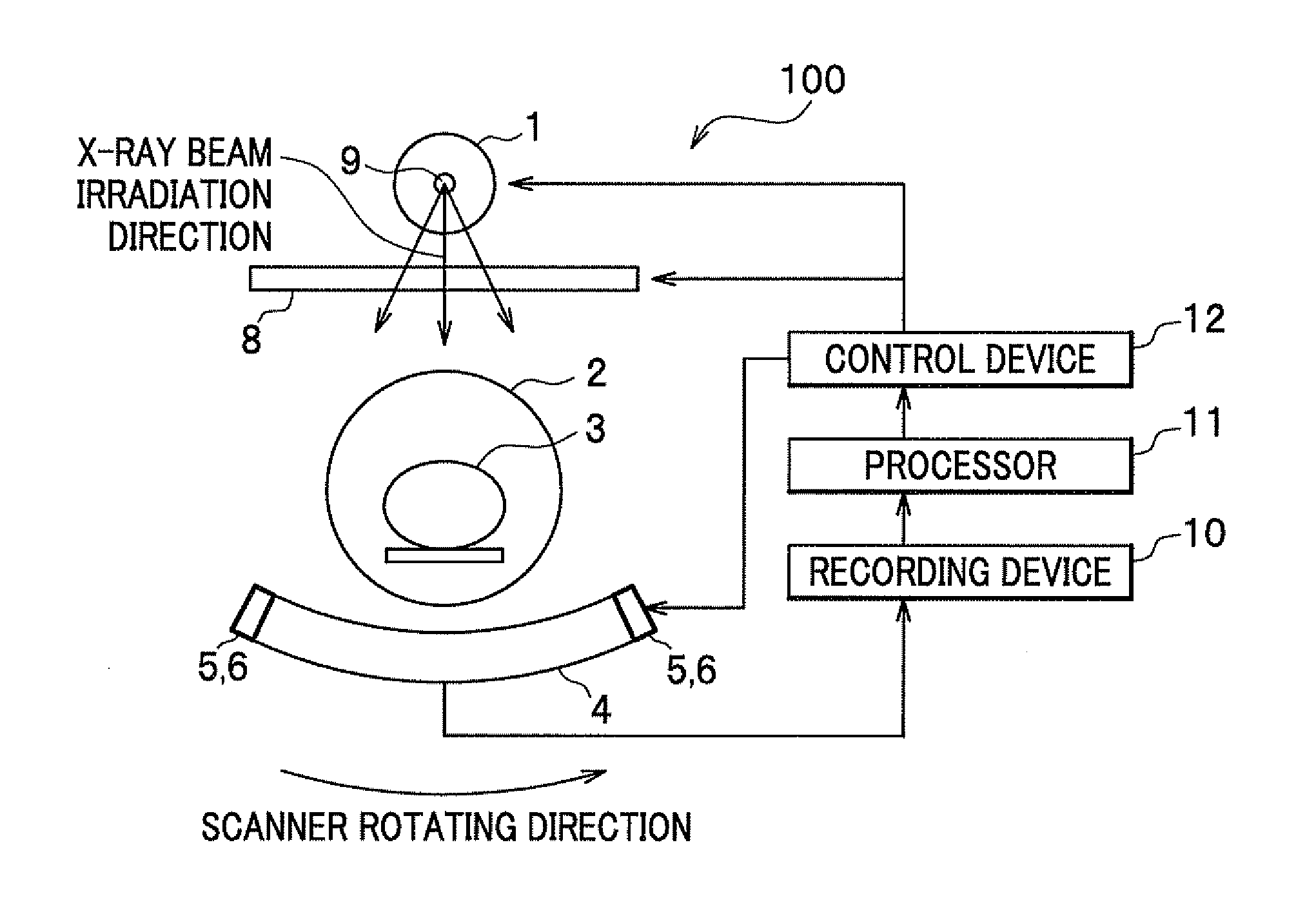
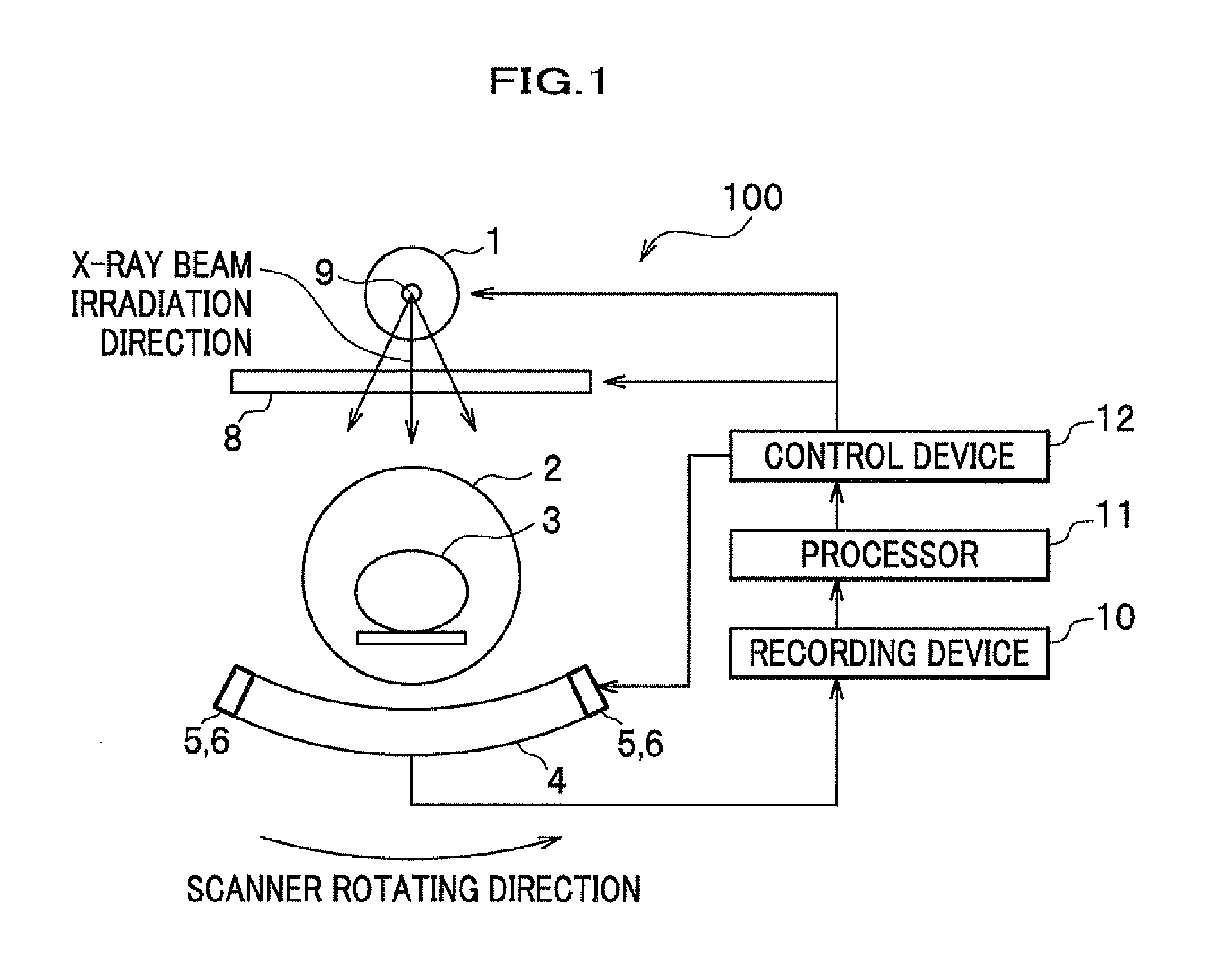
[0036]An explanation will be given of an X-ray CT device 100 according to a first embodiment of the present invention with reference to FIGS. 1, 2A and 2B.

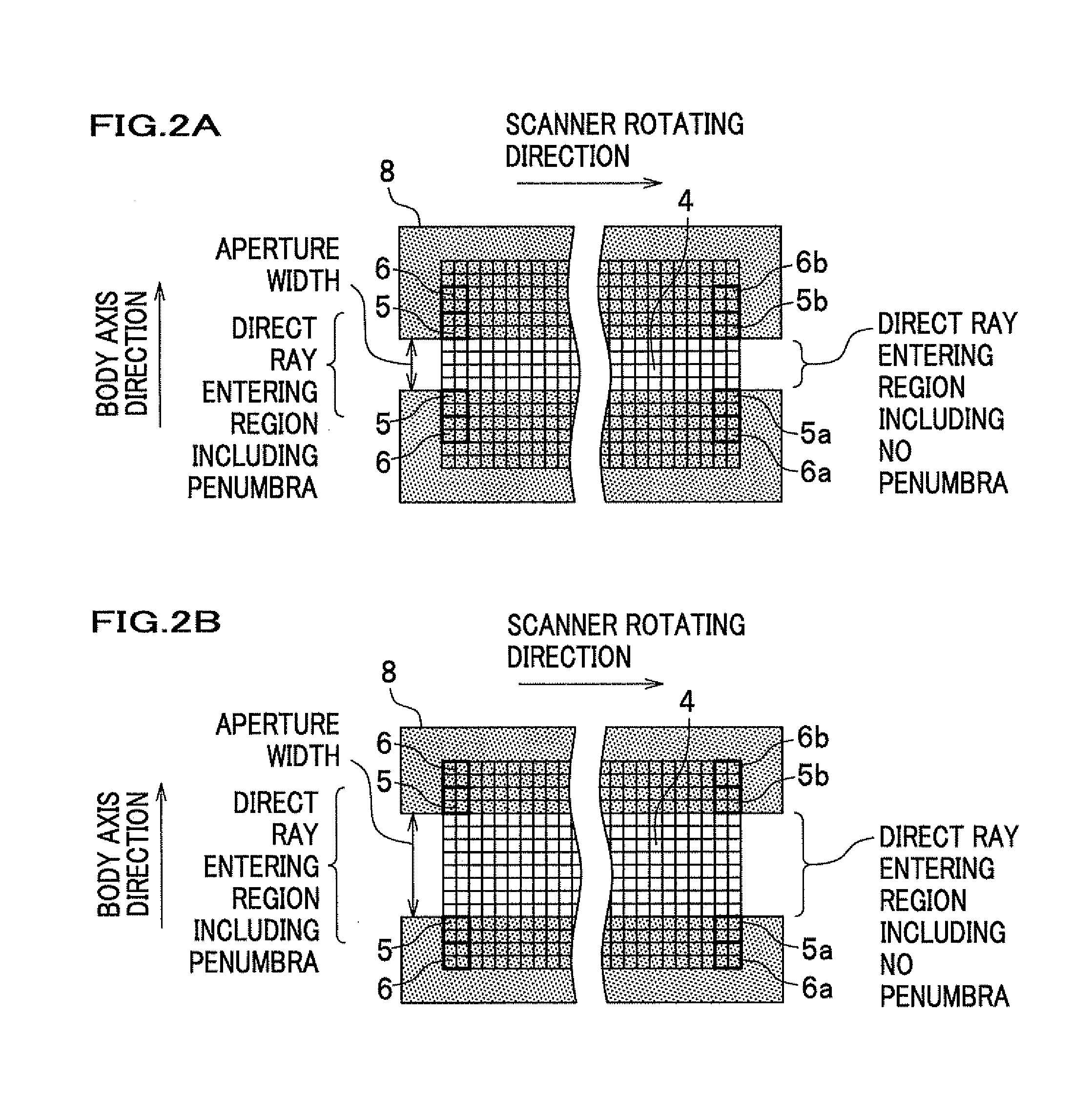
[0037]FIG. 1 is a diagram showing a configuration of an X-ray CT device according to the first embodiment of the present invention as viewed from a body axis direction. FIGS. 2A and 2B are diagrams each showing a configuration of the X-ray CT device according to the first embodiment of the present invention as viewed from an X-ray beam irradiation direction, and showing cases that the respective widths of the collimator apertures are different.

[0038]The X-ray CT device 100 has an unillustrated gantry that is provided at the center thereof with an opening 2 where an object 3 can enter.

[0039]The X-ray CT device 100 also has a scanner device that includes an X-ray tube 1 which is an X-ray source, a collimator 8, and an X-ray detector (or a main detector 4) for imaging an object. Those units are supported by the gantry in a rotatable ...

second embodiment

Modified Example of Second Embodiment

[0160]FIGS. 6, 7, and 8 show an X-ray CT device 201 according to a modified example of the second embodiment of the present invention.

[0161]FIG. 6 is a diagram showing a configuration of the X-ray CT device according to the modified example of the second embodiment of the present invention as viewed from the body axis direction. FIG. 7 is a diagram showing a configuration of the X-ray CT device according to the modified example of the second embodiment of the present invention as viewed from the X-ray beam irradiation direction. FIG. 8 is a schematic diagram showing a general configuration of the X-ray CT device according to the modified example of the second embodiment of the present invention when the slit has a plurality of apertures.

[0162]According to the X-ray CT device 200 of the second embodiment, the scattered X-ray detector 6 is disposed in the body axis direction of the shift detector 5, while the scattered X-ray detector 6 may be dispo...

third embodiment

[0171]The method of using the collimator 8 like the first embodiment and the method of providing the slits 7 like the second embodiment can be combined to carry out a method of forming a penumbra over the shift detector 5.

[0172]Detection of the positional shift of the X-ray focal point 9 and reference correction are both enabled through the following method using the same X-ray detector element row at the end of the main detector 4 in the scanner rotating direction.

[0173]FIGS. 16 and 17 show a geometrical arrangement of an X-ray CT device 300 according to a third embodiment of the present invention.

[0174]FIG. 16 is a diagram showing a configuration of the X-ray CT device according to the third embodiment of the present invention as viewed from a body axis direction. FIGS. 17A, 17B, and 17C are diagrams showing a configuration of the X-ray CT device according to the third embodiment of the present invention as viewed from an X-ray beam irradiation direction, and showing respective ca...


PUM


Abstract

Scattered X-rays scattered by an object or a structure enter in a detector (a shift detector) for detecting the positional shift of an X-ray focal point and become a noise source, thereby deteriorating the positional shift detection precision. In particular, the estimation of the dose of scattered X-rays originating from the object is difficult prior to the measurement, and correction of the scattered X-rays is important in order to precisely calculate the positional shift of the X-ray focal point. In order to address this drawback, according to the present invention, a scattered X-ray detector 6 is provided which measures the dose of scattered rays entering in a shift detector 5 for detecting the positional shift of an X-ray focal point 9, and has a function that the output by the shift detector 5 is corrected using the scattered ray dose measured by the scattered X-ray detector.

Description

TECHNICAL FIELD[0001]The present invention relates to an X-ray CT device.BACKGROUND ART[0002]X-ray CT (Computed Tomography) devices include an X-ray source that irradiates an object with X-rays, and an X-ray detector for imaging an object which is disposed at a position opposite to the X-ray source and for detecting X-rays passing through the object. Such devices reconstruct the differences in the X-ray absorption ratio inside the object as images using a data processing system based on projected data in plural directions obtained by rotational imaging around the object.[0003]In general, the X-ray source uses an X-ray tube that emits electrons accelerated by a high voltage to a positive electrode in order to generate X-rays. However, with respect to the energy used for accelerating the electrons, the generating efficiency of X-rays is low, and most energy is converted into heat. Hence, a phenomenon occurs which shifts the source where X-ray beams are generated due to the thermal exp...

Claims


Application Information

Patent Timeline
IPC IPC(8): A61B6/03
CPCA61B6/032A61B6/4208A61B6/58A61B6/4021A61B6/06
Inventor TSUBOTA, YUSHIWATANABE, FUMITOUEKI, HIRONORIKONNO, YASUTAKAKOJIMA, SHINICHISUZUKI, ATSURO
Owner HITACHI LTD
Why Eureka
Try Eureka