Apparatus and Method for Controlled Release of Lubricant Additives in Bearing and Gear Assemblies

a technology of additives and bearings, applied in the direction of manual lubrication, machines/engines, distribution equipment, etc., can solve the problems of not being present at sufficient quantity, not replenishing, and not providing sufficient quantity of additives in critical locations or wear surfaces, so as to reduce wear or oil oxidation during operation

Active Publication Date: 2012-07-05
THE TIMKEN CO
View PDF3 Cites 7 Cited by
  • Summary
  • Abstract
  • Description
  • Claims
  • Application Information

AI Technical Summary

Benefits of technology

[0006]Accordingly, it would be advantageous to provide lubricated surfaces such as those found in bearing components and gear assemblies, with a source of beneficial lubricant additives which can be released in a controlled manner in proximity to wear critical surfaces as required to minimize wear or oil oxidation during operation.

Problems solved by technology

However, with this traditional approach, once the additives are depleted from the lubricant, they are not replenished until fresh lubricant is supplied.
Furthermore, the additives are dispersed within the flow of lubricant through the entire lubrication system, and may not be present at sufficient quantity where needed, or may be depleted by reactions at non-critical or non-wear surfaces within the system.
While these systems provide for a slow release of additives into the flow of lubricant passing through the lubrication filer, they ultimately fail to ensure that sufficient quantity of the additives are provided a critical locations or wear surfaces, due to the uniform dispersion of the additives within the flow of lubricant.

Method used


Image

  • Apparatus and Method for Controlled Release of Lubricant Additives in Bearing and Gear Assemblies
  • Apparatus and Method for Controlled Release of Lubricant Additives in Bearing and Gear Assemblies
  • Apparatus and Method for Controlled Release of Lubricant Additives in Bearing and Gear Assemblies

Examples


Embodiment Construction

[0031]The following detailed description illustrates the invention by way of example and not by way of limitation. The description enables one skilled in the art to make and use the present disclosure, and describes several embodiments, adaptations, variations, alternatives, and uses of the present disclosure, including what is presently believed to be the best mode of carrying out the present disclosure.

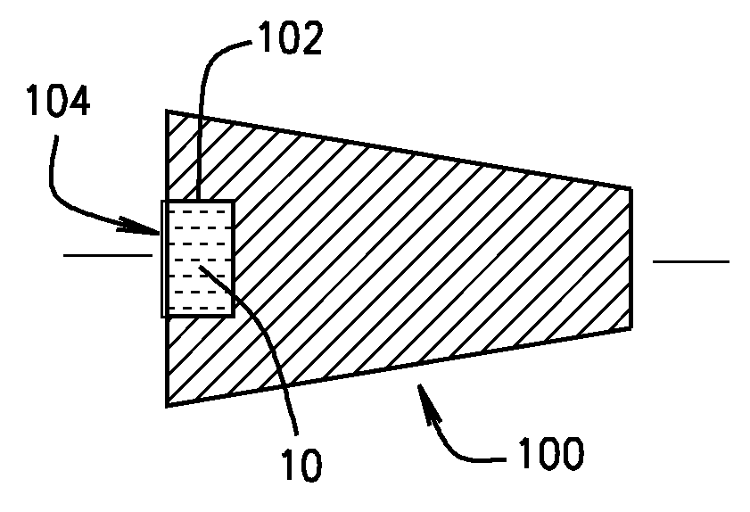
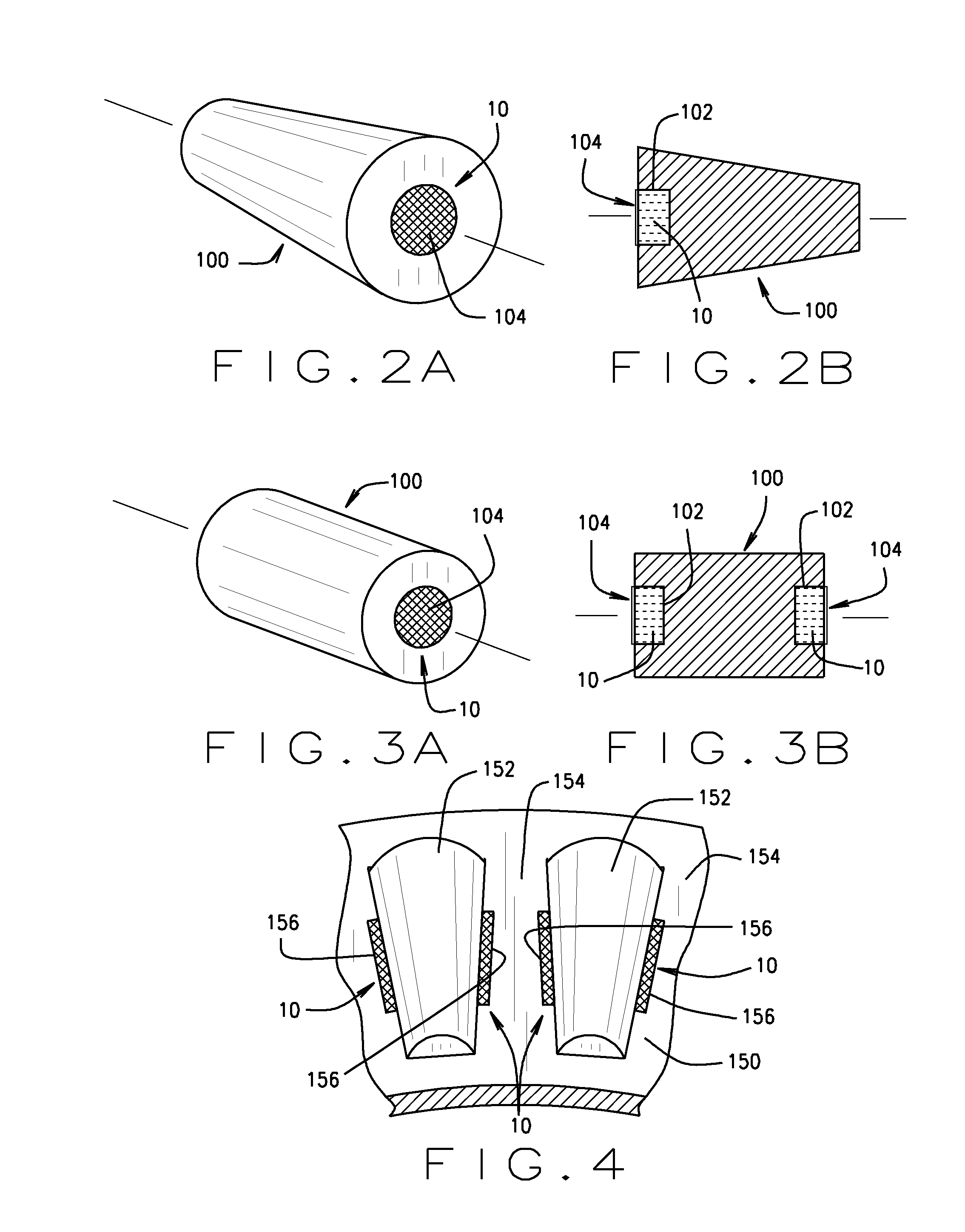
[0032]Lubricant additives retained or suspended in a gel form are not easily retained in their natural stage by specific placement within mechanical systems, such as friction management or power transmission systems shown in FIG. 1, as the mechanical properties of the gels are not suitable for adhesion onto a solid surface. Turning to the figures, and to FIG. 2A through FIG. 7 in particular, various components of mechanical systems such as rolling element bearings or gear assemblies are shown to be adapted with recessed regions in proximity to wear critical surfaces, to receive and ...


PUM


Abstract

A structure (200) for containing a volume of lubricant additive gel (10) which is disposed within a mechanical system, in close proximity to a wear critical surface, and which is configured to provide a release of the contained additives into a flow of lubricant over time or as a function of temperature in a site-specific manner to minimize wear or reduce oil oxidation due to harsh operating conditions. The structure defines a cage or capsule with screen or mesh sides (202) having multiple perforations or openings through which the flow of lubricant may circulate. Within the contained volume of the structure (200), additives are disposed in a gel matrix (10), and are release over time or as a function of temperature, through the perorations or openings, in close operative proximity to wear critical surfaces of the mechanical system such as a bearing assembly or gear arrangement.

Description

CROSS-REFERENCE TO RELATED APPLICATIONS[0001]The present application is related to, and claims priority from, U.S. Provisional Patent Application Ser. No. 61 / 242,017 filed on Sep. 14, 2009, and which is herein incorporated by reference.STATEMENT REGARDING FEDERALLY SPONSORED RESEARCH[0002]Not Applicable.BACKGROUND OF THE INVENTION[0003]The present application is related to the protection of bearing components and gear assemblies from wear or oil oxidation, and in particular to the protection of such components and assemblies by containing a volume of controlled-release additive gel in operative proximity to the bearing components and gear assemblies.[0004]Lubricant additive chemical technology is well known to improve the wear resistance of metallic surfaces. Similarly, anti-oxidant additives have been engineered to prolong the life of hydrocarbon lubricants by hindering oxidation reactions. The traditional approach for using these lubricant additives is to supply the additives with...

Claims


Application Information

Patent Timeline
Patent Type & Authority Applications(United States)
IPC IPC(8): F16C33/66F16N19/00F16H57/04
CPCC10N2250/10C10N2250/18F01M9/02Y10T74/19991F16C33/6651F16C33/6692F16C33/6696F16C33/6648C10N2050/10C10N2050/14F16C33/66F16H55/08F16H57/04
Inventor EVANS, RYAN D.SHILLER, PAUL J.PIERMAN, DAVID A.DOLL, GARY L.
Owner THE TIMKEN CO
Why Eureka
Try Eureka