
Wet Cell Arrangement for Rail Vehicles

a technology for rail vehicles and wet cells, which is applied in vehicle arrangements, transportation and packaging, railway bodies, etc., can solve the problems of large number of supply devices, such as wastewater piping for wet cells, and achieve the effect of reducing the amount of supply and disposal devices for wet cells

Inactive Publication Date: 2012-07-12
SIEMENS AG
View PDF8 Cites 0 Cited by
  • Summary
  • Abstract
  • Description
  • Claims
  • Application Information

AI Technical Summary

Benefits of technology

[0004]An object of the invention is to provide a wet cell arrangement, in which the expenditure on supply and disposal devices for the wet cells is reduced.
[0006]What is achieved thereby is that joint supply means can be used for particular components of the wet cells, and so, compared with the prior art, in which individual cabins are provided, a considerable potential saving can be obtained.
[0011]The two functional walls may each have a towel dispenser, which is arranged at least partially in the intermediate space. This means that the towel dispenser does not have to be accommodated fully in the associated wet cell. Instead, it is possible to use part of the intermediate space to hold optionally the entire towel dispenser, too, thereby saving space within the wet cell.
[0012]For a favorable configuration of the piping, but also an arrangement of the fan heater or of the towel dispenser, it may be favorable for the at least two wet cells to be formed in a mirror-symmetrical manner in relation to a vertical center plane of the intermediate space. In such cases, respective connections are opposite one another, thus allowing them to be combined in a simple manner to form a joint main line.

Problems solved by technology

It is generally regarded as disadvantageous in the construction of rail vehicles that any supply devices, such as wastewater piping for wet cells, for example, have to be provided in large numbers.

Method used


Image

  • Wet Cell Arrangement for Rail Vehicles
  • Wet Cell Arrangement for Rail Vehicles

Examples


Embodiment Construction

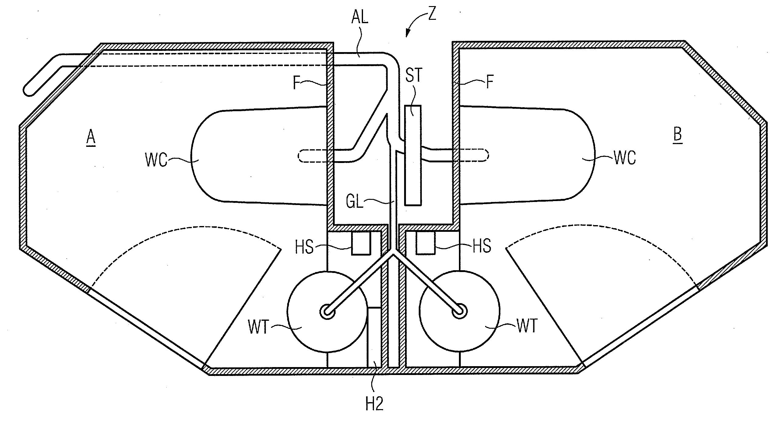
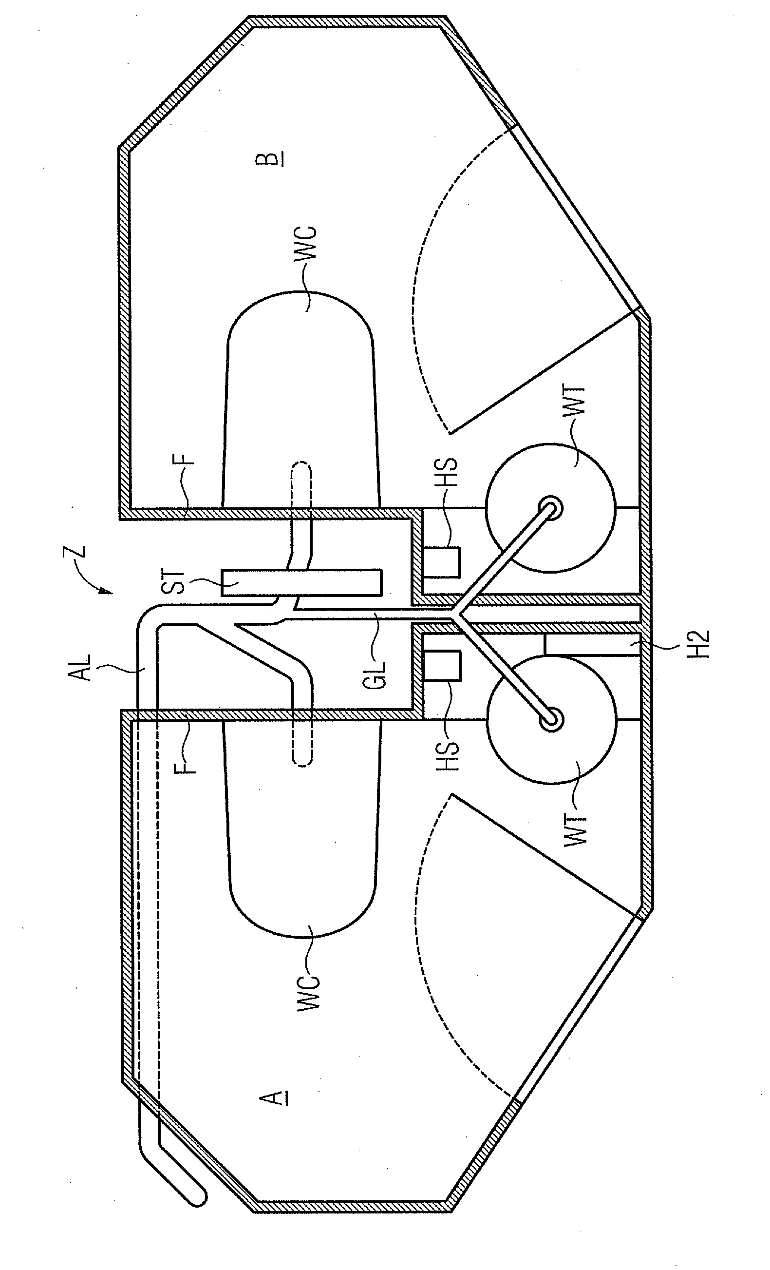
[0015]The wet cell arrangement shown in the figure has two wet cells A, B, wherein walls which face one another of the wet cells A, B are formed as functional walls F. The functional walls F are located opposite one another and are spaced apart from one another such that an intermediate space Z is produced, said intermediate space Z serving to accommodate jointly used functional elements.

[0016]The wet cells A, B are formed in a mirror-symmetrical manner in relation to a vertical center plane of the intermediate space Z and have a toilet WC, a washbasin WT with an associated faucet, soap dispenser and towel dispenser HS.

[0017]Gray-water piping is connected by way of two branches to the washbasins WT. The two branches combine to form a common main gray-water line GL, which leads to the wastewater tank. The two toilets WC are connected to respective wastewater piping branches, said wastewater piping opening into a main wastewater line AL, which leads to a wastewater tank.

[0018]The towe...


PUM


Abstract

A wet cell arrangement for a carriage body of a rail vehicle is provided. The carriage body includes two wet cells which are bounded in each case on one side by a functional wall. The functional walls are arranged in a manner spaced apart from and facing one another. Jointly useable supply and disposal lines are arranged in an intermediate space between the two functional walls of the two wet cells.

Description

FIELD OF INVENTION[0001]The invention relates to a wet cell arrangement for a carriage body of a rail vehicle, having at least two wet cells arranged in the carriage body.BACKGROUND OF INVENTION[0002]It is known in the field of rail vehicles to provide individual carriage bodies with a plurality of wet cells, typically two. In a first, known embodiment, the wet cells are in the form of individual cabins, which are arranged opposite one another in the carriage body. Furthermore, there is what is known as a “twin combination” of two wet cells, which is characterized in that two wet cells are arranged in succession. In this known embodiment, too, the character of the wet cell remains that of autonomous individual cabins.[0003]It is generally regarded as disadvantageous in the construction of rail vehicles that any supply devices, such as wastewater piping for wet cells, for example, have to be provided in large numbers.SUMMARY OF INVENTION[0004]An object of the invention is to provide ...

Claims


Application Information

Patent Timeline
IPC IPC(8): B61D35/00B60N3/00B61D1/00B61D17/00
CPCB61D35/00
Inventor VAN LIESHOUT, SANDER
Owner SIEMENS AG
Learn More