Liner tube with non-stretching material

a non-stretching material and liner tube technology, applied in the direction of pipes/joints/fittings, pipe elements, mechanical devices, etc., can solve the problems of limiting radial stretching, not being able to use liner tubes, and not being able to use scrims

Active Publication Date: 2012-07-12
LMK TECH LLC
View PDF11 Cites 16 Cited by
  • Summary
  • Abstract
  • Description
  • Claims
  • Application Information

AI Technical Summary

Benefits of technology

[0010]It is another object, feature, and/or advantage of the present invention to provide an improved liner tube for lining a lateral pipe that will not substantially stretch longitudinally, but that will allow for radial stretching.
[0011]It is another object, feature, and/or advantage of the present invention to provide a liner assembly that can be inverted into a lateral pipe to cover and repair only an area of the lateral pipe in need of repair.
[0012]It is another object, feature, and/or advantage of the present invention to provide a method and means of lining a lateral pipe that does not require cutting any of the liner after curing the material to reinstate servic

Problems solved by technology

One problem that commonly arises involves the type of liner tube used to make the repair.
While precautions may be taken to avoid the liner tube extending into the main pipe, problems exist with the current solutions.
However, the woven scrims, while limiting longitudinal stretching, also limit radial stretching.
The scrims do not allow for the liner tube to be fully pressed a

Method used


Image

  • Liner tube with non-stretching material
  • Liner tube with non-stretching material
  • Liner tube with non-stretching material

Examples


Embodiment Construction

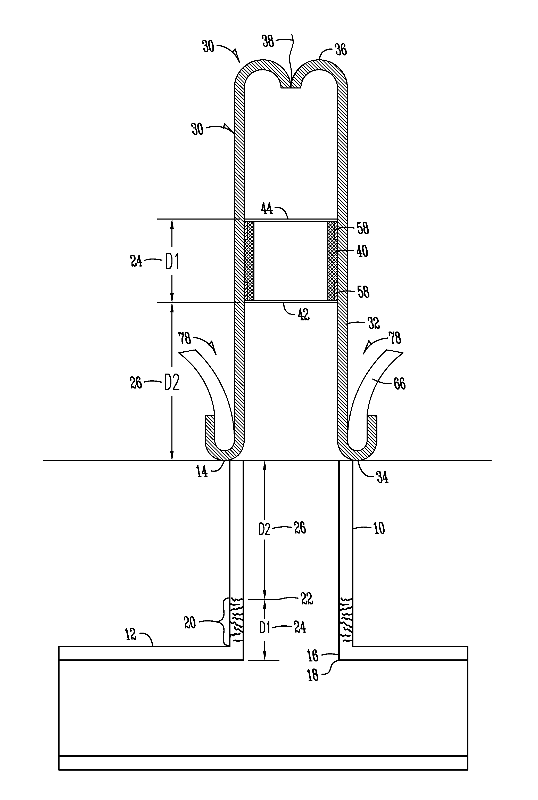
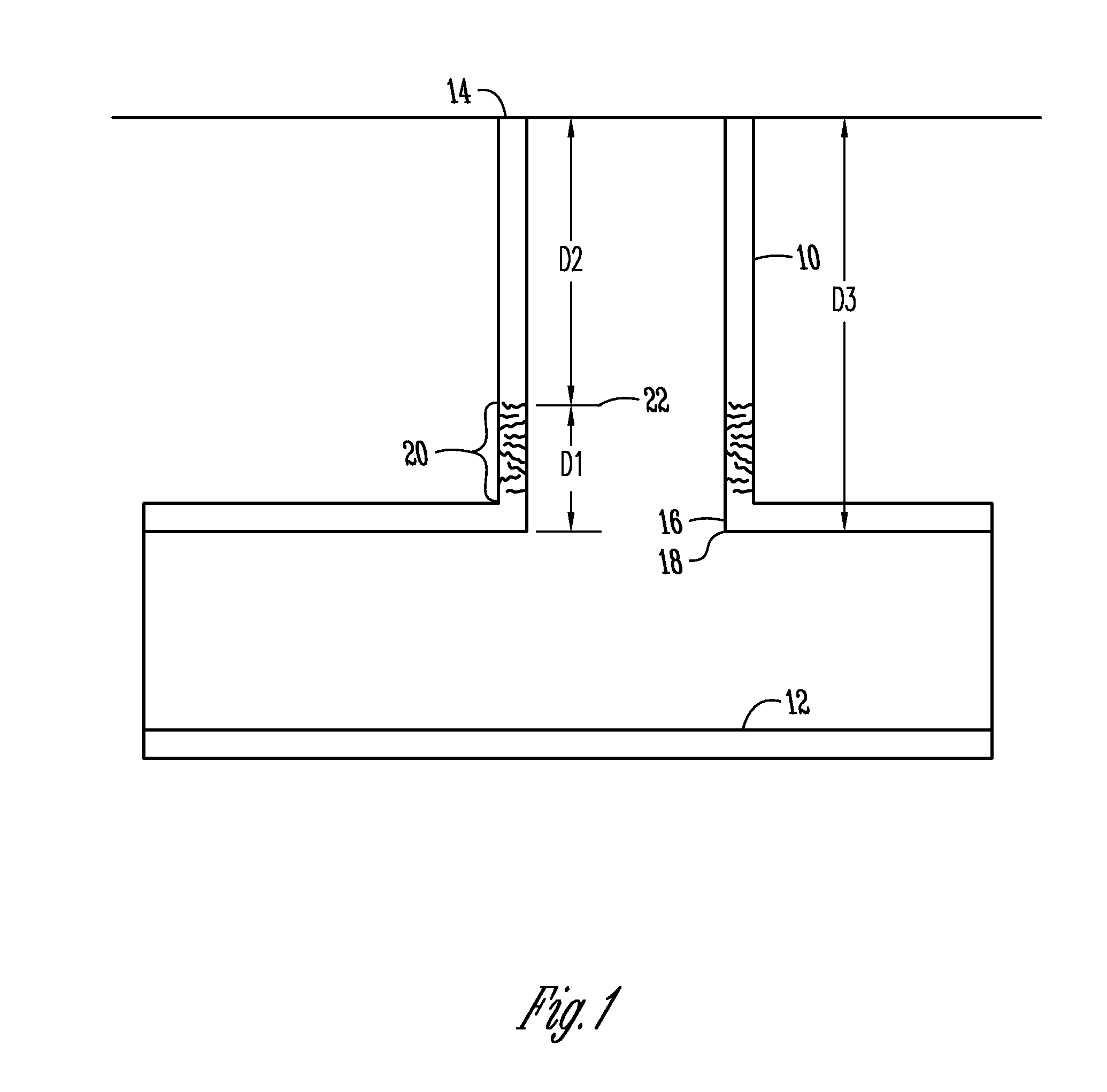
[0030]FIG. 1 is a sectional view of an exemplary structure of how a lateral pipe 10 and main pipe 12 are configured. Generally, a main pipe 12 would be located between two manholes (not shown) with the lateral pipe 10 branching off from the main pipe 12 towards a house, or other structure. While FIG. 1 shows the lateral pipe 10 branching from the main pipe 12 in a tee-shape, or approximately 90°, it should be appreciated that the lateral pipe 10 may also branch off from the main pipe 12 at other angles, including wye-shaped structures. As is further shown in FIG. 1, the lateral pipe 10 may have a first or launching end 14 and an opposite second end 16, which ends at a juncture 18 between the lateral pipe 10 and the main pipe 12. Therefore, the lateral pipe 10 has a length, shown as D3 in FIG. 1. Due to changing conditions around the lateral pipe 10 including a change in the soil, environment, or vegetation surrounding the lateral pipe 10, the lateral pipe 10 may form damage spots. I...


PUM


Abstract

An apparatus and method of making a cured-in-place pipe repair to a lateral pipe having an area in need of repair. The method and apparatus use a liner assembly comprising a bladder tube and a liner tube. The liner tube comprises at least one layer of non-stretching material, which includes strands of non-stretching material oriented in the longitudinal direction of the liner tube. The strands allow radial stretching but ensure that the liner tube does not stretch longitudinally, which prevents the liner tube from stretching into a main pipe or past the area in need of repair during use. The liner tube may also comprise second and third layers of a resin impregnable material, such as felt, which surround the layer of non-stretching material such that the liner tube may be impregnated with a resinous material to repair a pipe having an area in need of repair.

Description

FIELD OF THE INVENTION[0001]The present invention generally relates to a method and means of repairing a pipe. More particularly, but not exclusively, the invention relates to a method and means of a cured-in-place pipe (CIPP) repair for use in repairing a lateral pipe with an access pipe and having an area in need of repair and that ends at a juncture with a main pipe.BACKGROUND OF THE INVENTION[0002]Cured-in-place pipe (CIPP) repair has been used to repair damaged main sewer pipes or lateral sewer pipes as well as other types of conduits. Generally, a liner tube is impregnated with a resinous material and is positioned in a pipe adjacent a damaged area of pipe. The liner tube is pressed against the wall of the damaged area of the pipe and the resin is allowed to cure, thus leaving a renewed pipe wall. The liner tube is either pulled in place or inflated and inverted into the pipe to the damaged area in need of repair.[0003]At times, only a specific section of a lateral pipe needs ...

Claims


Application Information

Patent Timeline
IPC IPC(8): F16L55/16
CPCF16L55/1651F16L55/179F16L55/1656
Inventor KIEST, JR., LARRY W.
Owner LMK TECH LLC
Why Eureka
Try Eureka