RFID tag holder

Inactive Publication Date: 2012-07-12
CHINA STEEL
View PDF5 Cites 6 Cited by
  • Summary
  • Abstract
  • Description
  • Claims
  • Application Information

AI Technical Summary

Benefits of technology

[0010]The RFID tag holder according to the present invention is suitable for installing RFID tag on any kind of apparatuses or devices, and has the following advantages:
[0012]2. Suitable for disposing holes with any depth and size, thus improving the flexibility in application.
[0013]3. Disposing holes with different depth will not induce interference with the RFID tag, and the reading effect is improved.
[0014]4. The holder can be directly disposed in the disposing hole of a device (for example a roller), and extra processing cost for the device is not needed.
[0016]6. The number of the holding clips of the holding unit can be increased or reduced according to actual needs for better composability, extensibility and flexibility.

Problems solved by technology

In the case of huge objects or apparatuses, though, RFID tags cannot be firmly attached, and therefore are mostly installed by screws.
However, most apparatuses are made of metal, and the drilling and tapping processing cause an extremely high cost, and the structure and characteristic of the original apparatuses cannot be maintained and guaranteed after drilling.
However, after the roller is used, the code often becomes unintelligible because it may be covered by grease, dirt, water stain or identification painting.
Moreover, in the case of rollers without grooves on the side surface, if the RFID tags are installed directly on the side surface, when the rollers are ground, the RFID tags will be crashed and destroyed by the dowel disc.
Therefore, the conventional technique for installing RFID rollers requires high cost for its installing and processing.

Method used


Image

  • RFID tag holder
  • RFID tag holder
  • RFID tag holder

Examples


first embodiment

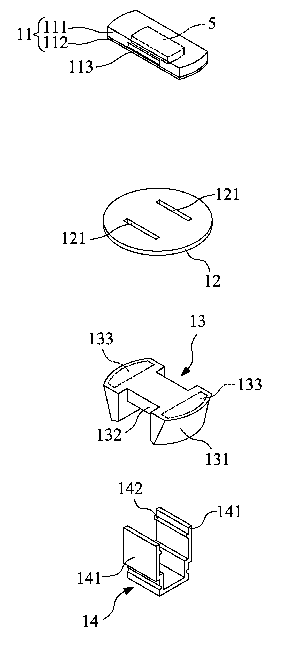
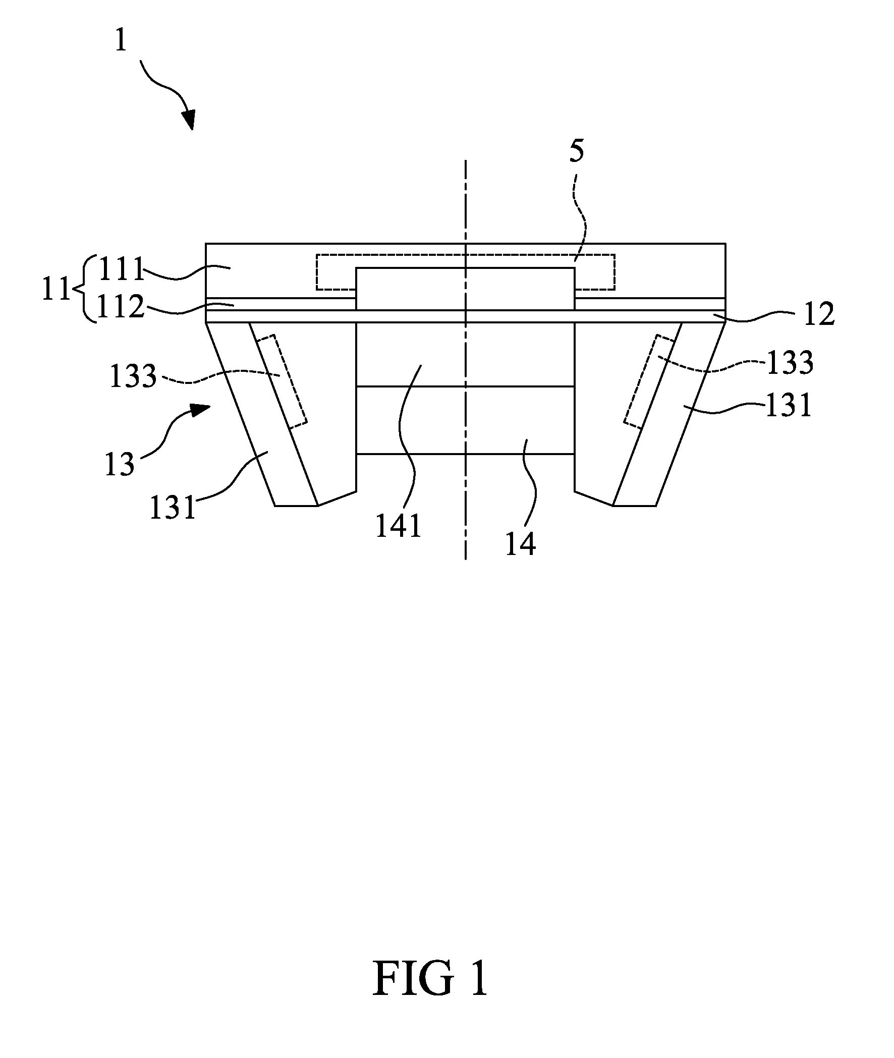
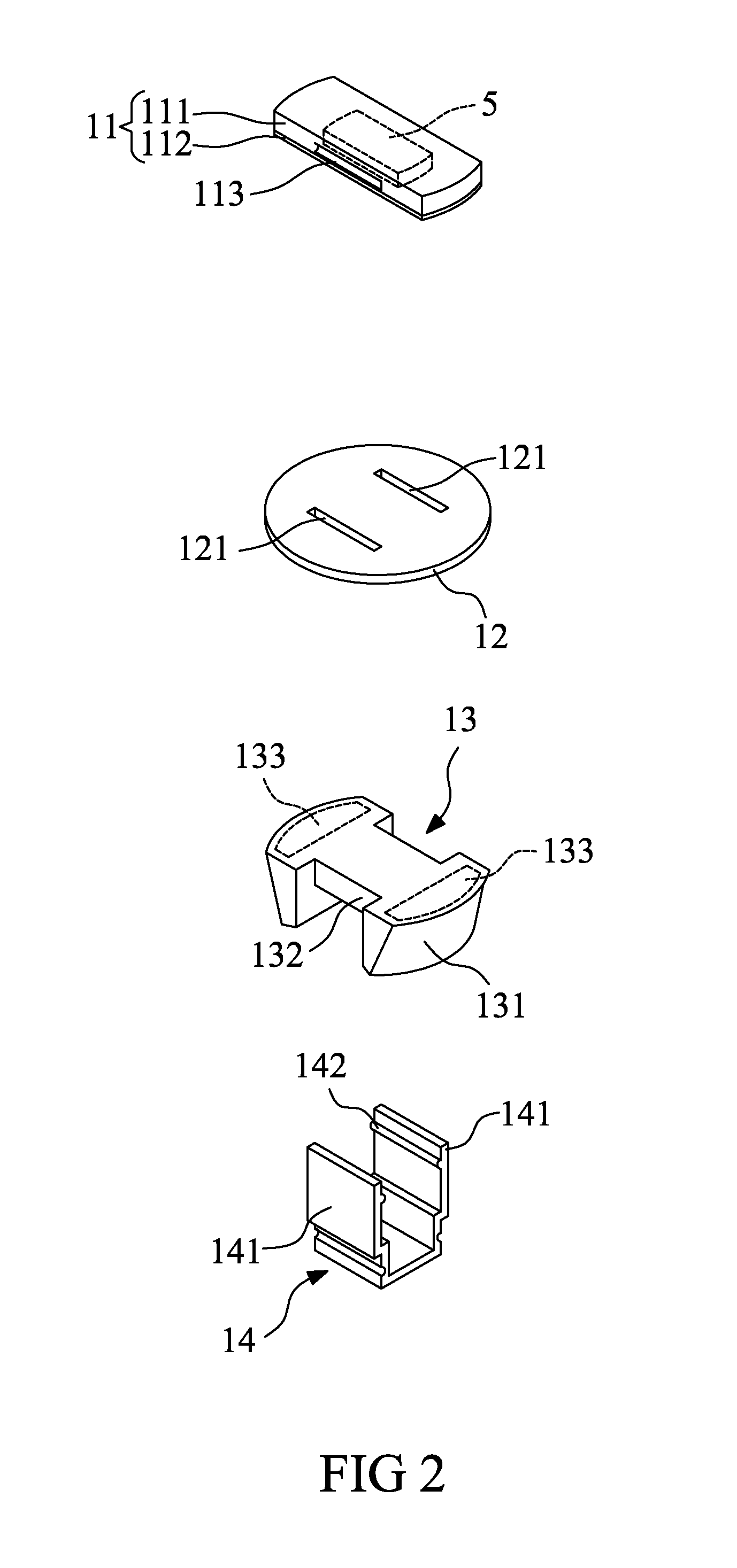
[0031]In the embodiment, the difference between the three stacked holding clips 241, 242, 243 and the RFID tag holder 1 as shown above in FIGS. 1 and 2 is that, in the embodiment, two clip arms 2411 of a bottom holding clip 241 grip the holding portion 132 after stacking, the first holding structures 2412 of the clip arms 2411 hold the third holding structures 2423 disposed at the bottom of the adjacent middle holding clip 242, the first holding structures 2422 of the clip arms 2421 of the middle holding clip 242 hold the third holding structures 2433 disposed at the bottom of a top holding clip 243 after stacking, and the first holding structures 2432 thereof hold the second holding structures 113 of the RFID tag carrier 11 after two clip arms 2431 of the top holding clip 243 passing through the through holes 121 of the metal substrate 12.

[0032]Preferably, the size and shape of the metal substrate 12 match those of a second depth position (disposed close to the opening of the disp...

second embodiment

[0035]Preferably, the size and shape of the metal substrate 12 match those of a fourth depth position (disposed close to the opening of the disposing hole) of the disposing hole, and the size and shape of the bottom plate 41 and the base 43 are match those of a fifth depth position (disposed far away from the opening of the disposing hole) of the disposing hole, thereby increasing the combination stability of the RFID tag holder 4 and the disposing hole. The other elements which are the same as the RFID tag holder 2 as shown above in FIGS. 4 and 5 are designated by the same reference numbers, and therefore the description is skipped.

[0036]The RFID tag holder according to the present invention is suitable for installing RFID tag on any kind of apparatuses or devices, and has the following advantages:

[0037]1. Fast installation, low cost and reusability.

[0038]2. Suitable for disposing holes with any depth and size, and the flexibility is improved.

[0039]3. Disposing holes with differen...


PUM


Abstract

The present invention relates to an RFID tag holder, which comprises an RFID tag carrier used to carry an RFID tag, and a base having a circular surface, a holding portion and at least one magnetic component disposed therein. The shape of the circular surface matches that of the disposing hole, the magnetic component is used to make the disposing hole magnetically attachable to combine the base with the disposing hole, and two clip arms of a holding unit grip the holding portion and hold the RFID tag carrier after passing through two through holes of a metal substrate. The RFID tag holder has the following advantages: fast installation, low cost and reusability; is suitable for disposing holes with any depth and size; reduced interference and improved reading effect; no extra processing cost; dust-proof, water-proof and oil-resistant; and better composability, extensibility and flexibility.

Description

BACKGROUND OF THE INVENTION[0001]1. Field of the Invention[0002]The present invention relates to an RFID tag holder, and more particularly to a magnetically attached RFID tag holder.[0003]2. Description of the Related Art[0004]The application of RFID (Radio Frequency Identification) tags is universal, and has obvious effect especially on the logistics management of commodity supply chain. RFID tags are mostly directly attached to packing cases or cartons, in which case tag attaching is not a big problem. In the case of huge objects or apparatuses, though, RFID tags cannot be firmly attached, and therefore are mostly installed by screws.[0005]However, most apparatuses are made of metal, and the drilling and tapping processing cause an extremely high cost, and the structure and characteristic of the original apparatuses cannot be maintained and guaranteed after drilling. Therefore, how to overcome problems in RFID technique for industry application and how to install the designed RFID...

Claims


Application Information

Patent Timeline
IPC IPC(8): F16M13/00H01F7/02
CPCG06K19/07758Y10T24/45775Y10T24/3651
Inventor CHEN, SUNG-LINLIN, CHANG-TSUNCHIANG, LIEN-KUEI
Owner CHINA STEEL
Why Eureka
Try Eureka