Image sensors and methods with shared control lines

a technology of image sensors and control lines, applied in the field of image sensors with control lines, can solve the problem that the technology of sharing readout circuitry does not work for a 5t pixel, and achieve the effect of reducing the number of control lines crossing a pixel, increasing the useful area of pixels, and reducing the number of control lines crossing

Active Publication Date: 2012-07-12
KRYMSKI ALEXANDER
View PDF6 Cites 28 Cited by
  • Summary
  • Abstract
  • Description
  • Claims
  • Application Information

AI Technical Summary

Benefits of technology

[0028]Embodiments of the present invention allow for reducing a number of control lines crossing a pixel array by adding additional column readout lines and / or employing particular readout methods, and sharing control lines among two or more rows and / or columns of pixels in the pixel array. For example, in various embodiments there are two vertical column readout lines for each column of pixels in the pixel array, and all of the horizontal control lines extending across the pixel array for carrying signals to control pixels are shared among a corresponding two rows of pixels in the pixel array. In various other embodiments, there are four vertical column readout lines for each column of pixels in the pixel array, and all of the horizontal control lines extending across the pixel array for carrying signals to control pixels are shared among a corresponding four rows of pixels in the pixel array. Reducing a number of control lines crossing a pixel array allows for increasing a useful area for pixels, because less space is needed for the control lines. In various embodiments, two adjacent rows of a global shutter pixel array have common control lines, which allows for a smaller pixel size or for higher pixel sensitivity for a same pixel size.

Problems solved by technology

As a consequence, the technique to share readout circuitry does not work for a 5T pixel, because the 5T pixel uses the readout node for storing charge for the shuttered signal and, thus, the readout node is individual to a particular pixel and cannot be shared with other pixels.

Method used


Image

  • Image sensors and methods with shared control lines
  • Image sensors and methods with shared control lines
  • Image sensors and methods with shared control lines

Examples


Embodiment Construction

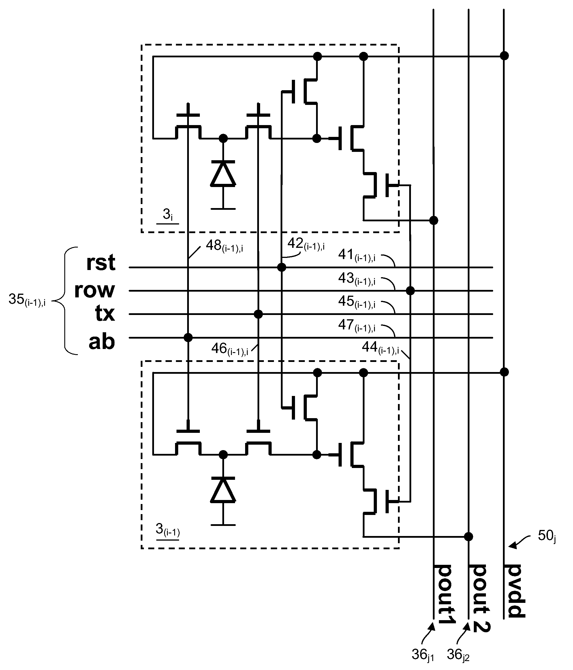
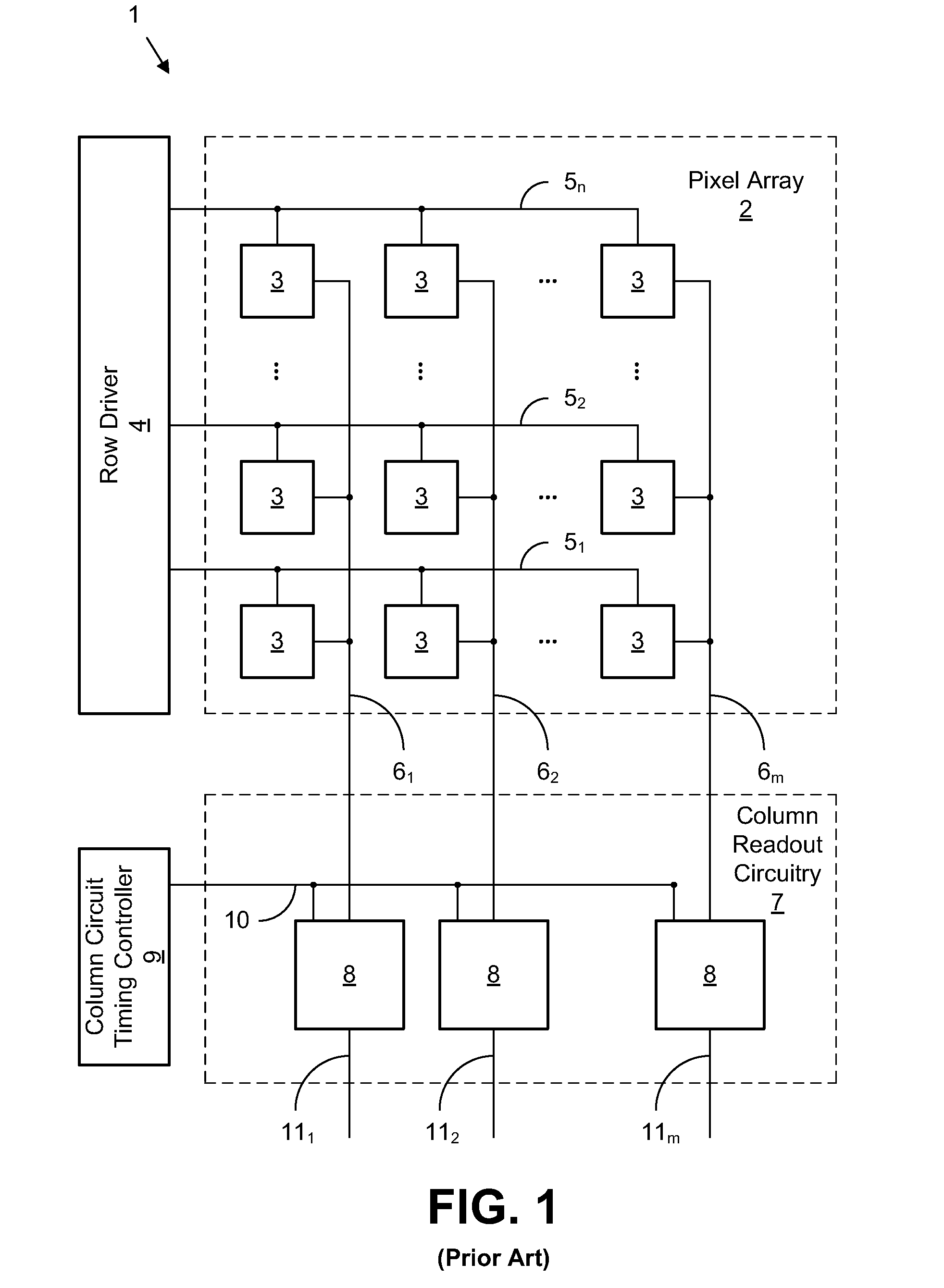
[0043]FIG. 5 illustrates a block diagram of an image sensor 31 in accordance with an embodiment of the present invention. The image sensor 31 includes a pixel array 32, a row driver 34, top column readout circuitry 37a, and bottom column readout circuitry 37b. In various embodiments, the image sensor 31 may be, for example, a high speed complimentary metal oxide semiconductor (CMOS) image sensor, or the like.

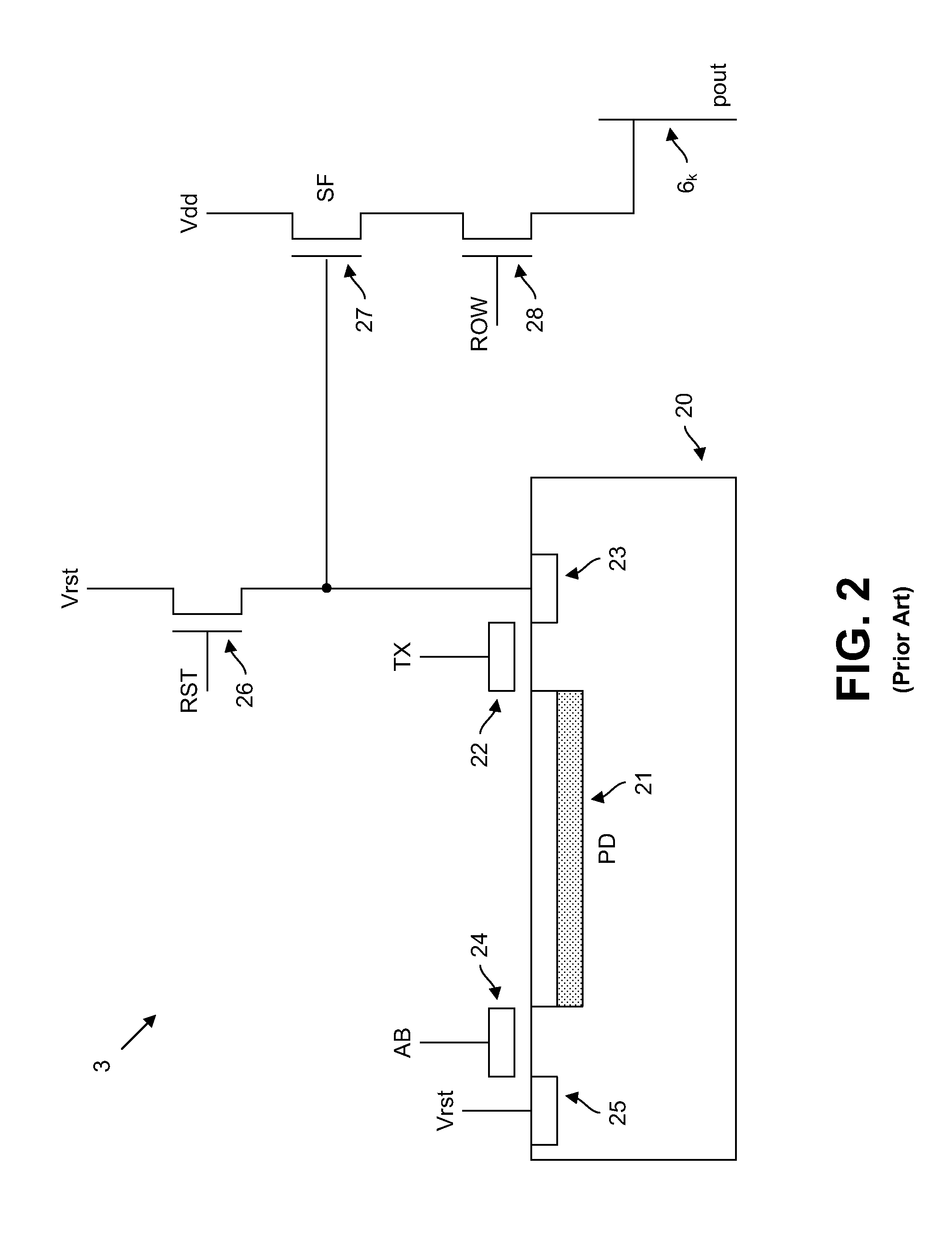
[0044]The pixel array 32 includes a plurality of pixels 3 arranged in a plurality of rows and a plurality of columns. For example, the pixels 3 in the pixel array 32 may be arranged in n rows and m columns, where n and m are integer values. Each pixel 3 of the pixel array 32 is configured to sample light intensity and to provide a corresponding analog pixel signal based on the sampled light intensity. In various embodiments, each pixel 3 is a five transistor (5T) pixel with an architecture as illustrated in FIGS. 2 and 3. In various other embodiments, other types of pixels may b...


PUM


Abstract

An image sensor includes a pixel array with a plurality of pixels. Two or more rows of pixels in the pixel array share a control line in the pixel array, and pixels of the two or more rows of pixels that are in a same column of the pixel array are connected to provide output to different column readout lines. A method includes providing a control signal over a control line within a pixel array to pixels in two or more rows of the pixel array, and reading out signals from the pixels in the two or more rows at a same time over different column readout lines. An image sensor includes a pixel array with a plurality of pixels, and two or more columns of pixels in the pixel array may share a control line in the pixel array for receiving a control signal.

Description

CROSS-REFERENCE TO RELATED PATENT APPLICATIONS[0001]This application claims priority from U.S. Provisional App. Ser. No. 61 / 431,387, filed Jan. 10, 2011, the entire contents of which are incorporated by reference herein.BACKGROUND OF THE INVENTION[0002]1. Field of the Invention[0003]Embodiments of the present invention relate generally to image sensors and methods and, in specific embodiments, to image sensors with control lines that provide control signals to pixels.[0004]2. Related Art[0005]Image sensors have found wide application in consumer and industrial electronics, and have enabled an explosion in a number of digital cameras and digital video devices used for work and entertainment.[0006]FIG. 1 illustrates an architecture of a related art image sensor 1. The image sensor 1 includes a pixel array 2, a row driver 4, column readout circuitry 7, and a column circuit timing controller 9. The pixel array 2 includes pixels 3 that are arranged in rows and columns. Each pixel 3 inclu...

Claims


Application Information

Patent Timeline
Patent Type & Authority Applications(United States)
IPC IPC(8): H01L27/148
CPCH01L27/14609H01L27/14654H01L27/14641
Inventor KRYMSKI, ALEXANDER
Owner KRYMSKI ALEXANDER
Why Eureka
Try Eureka