

Resilient bridge support having a piezoelectric device
- Summary
- Abstract
- Description
- Claims
- Application Information
AI Technical Summary
Benefits of technology
Problems solved by technology
Method used
Image

Examples
Example
[0020]
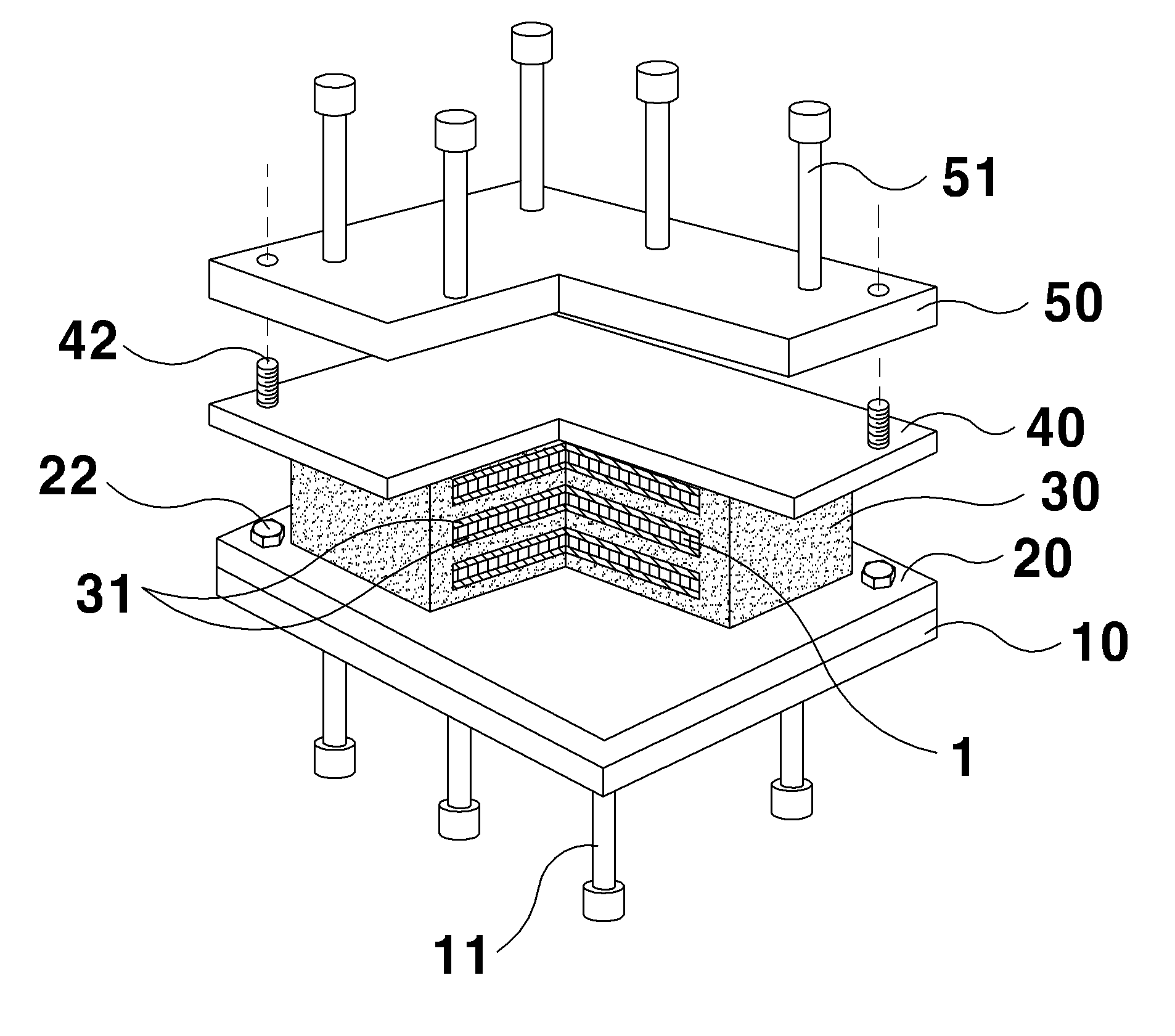
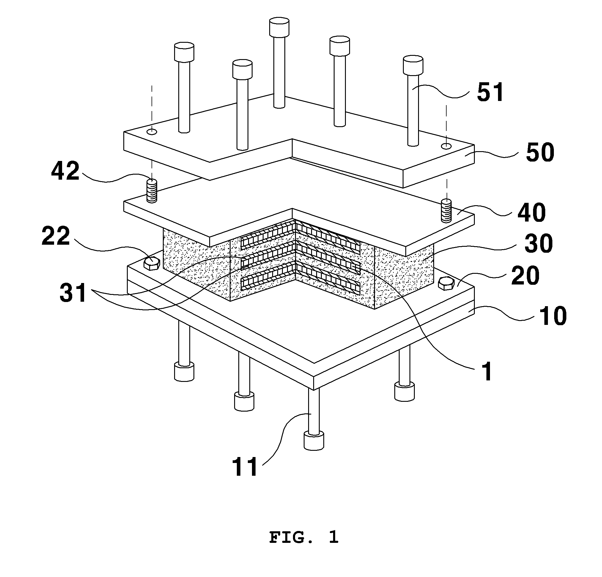
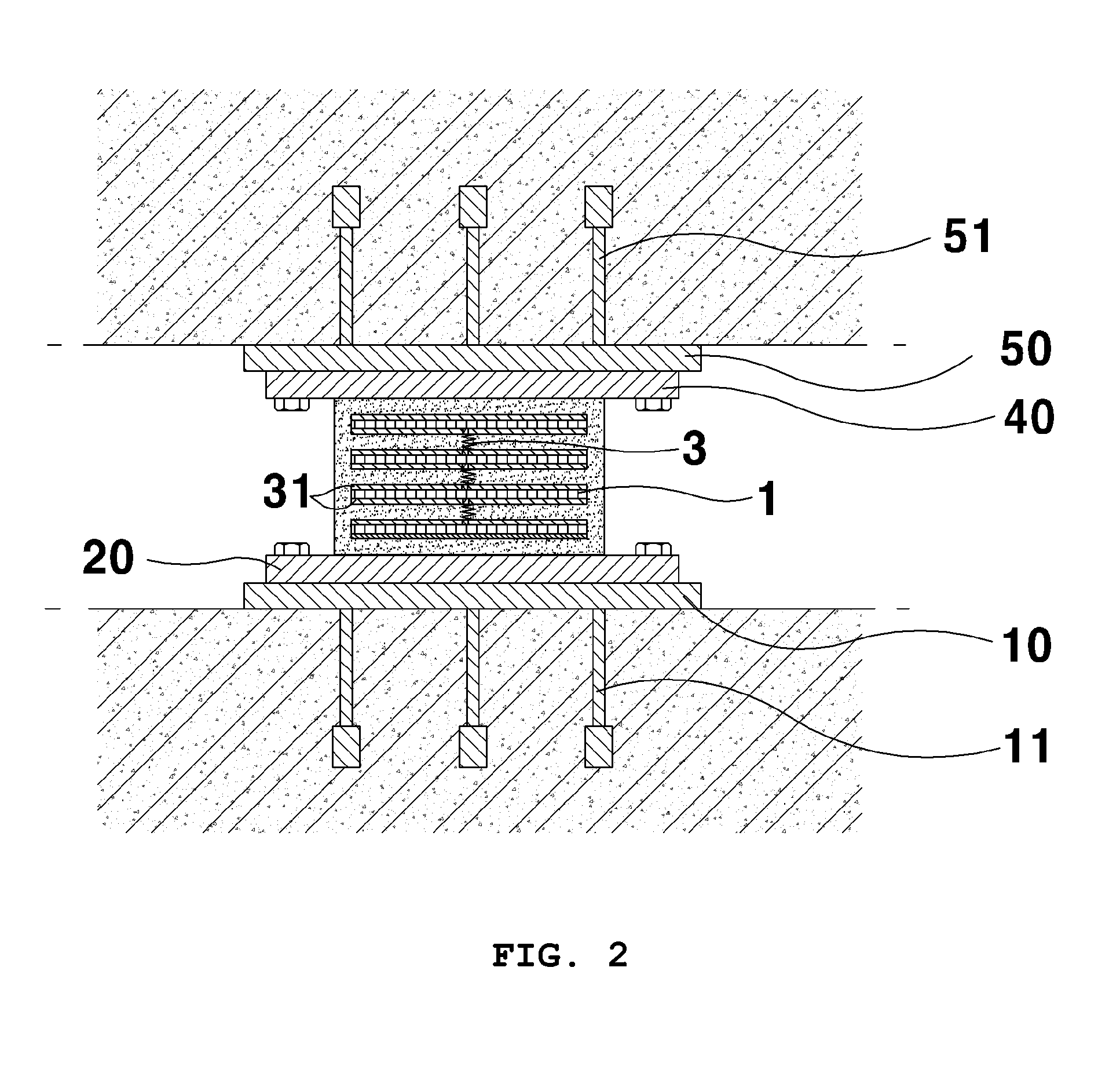
1: piezoelectric element2: storage battery3: coil-shaped electric wire10: base plate11: anchor socket20: lower mounting plate22, 42: fastening bolt30: rubber pad31: steel plate31a: electric wire guide hole32: projection33: paraffin layer34: cut-out portion40: upper mounting plate50: upper plate51: anchor socket
BEST MODE
[0021]Reference will now be made in greater detail to preferred embodiments of the invention with reference to the accompanying drawings.
[0022]Firstly, a general structure of a resilient bridge support having piezoelectric elements according to the present invention will be described. The resilient bridge support includes an upper plate 50 fixedly installed on a bottom surface of a superstructure (deck plate) of a bridge, a base plate 10 fixedly installed on a top surface of an infrastructure (pier) of the bridge, an upper mounting plate 40 and a lower mounting plate 10 each fixed on opposing surfaces of the upper plate 50 and the base plate 10, and a rubber pad...
PUM
 Abstract
Description
Claims
Application Information