Lighting device, display device, and television receiver

a technology of display device and light source, which is applied in the direction of lighting and heating apparatus, television systems, instruments, etc., can solve the problems of unstable shape of rising portion, increased production cost, and increased production cost, and achieve the effect of suppressing uneven brightness

Inactive Publication Date: 2012-07-12
SHARP KK
View PDF10 Cites 11 Cited by
  • Summary
  • Abstract
  • Description
  • Claims
  • Application Information

AI Technical Summary

Benefits of technology

[0008]The rising portion of the reflection sheet is formed to rise from the bottom portion to the light exit side. Accordingly, a rising angle from the bottom portion may change or deformation such as warpage or bending is likely to occur, for example. Thus, the shape of the rising portion tends to be unstable. In this regard, according to the present invention, the rising portion is sandwiched between the first holding member, that is arranged on a side opposite to the light exit side with respect to the rising portion and fixed to the chassis, and the second holding member, that is arranged on the light exit side of the rising portion, thereby regulating the displacement of the rising portion to the light exit side and to the side opposite to the light exit side. This can suppress change of the rising angle of the rising portion with respect to the bottom portion, and can suppress occurrence of deformation such as warpage or bending in the rising portion. That is, the shape of the rising portion can be stably kept. Therefore, the directivity of the reflected light can be stabilized, so that unevenness hardly occurs in the light exited from the lighting device.

Problems solved by technology

Accordingly, a rising angle from the bottom portion may change or deformation such as warpage or bending is likely to occur, for example.
Thus, the shape of the rising portion tends to be unstable.

Method used


Image

  • Lighting device, display device, and television receiver
  • Lighting device, display device, and television receiver
  • Lighting device, display device, and television receiver

Examples


first embodiment

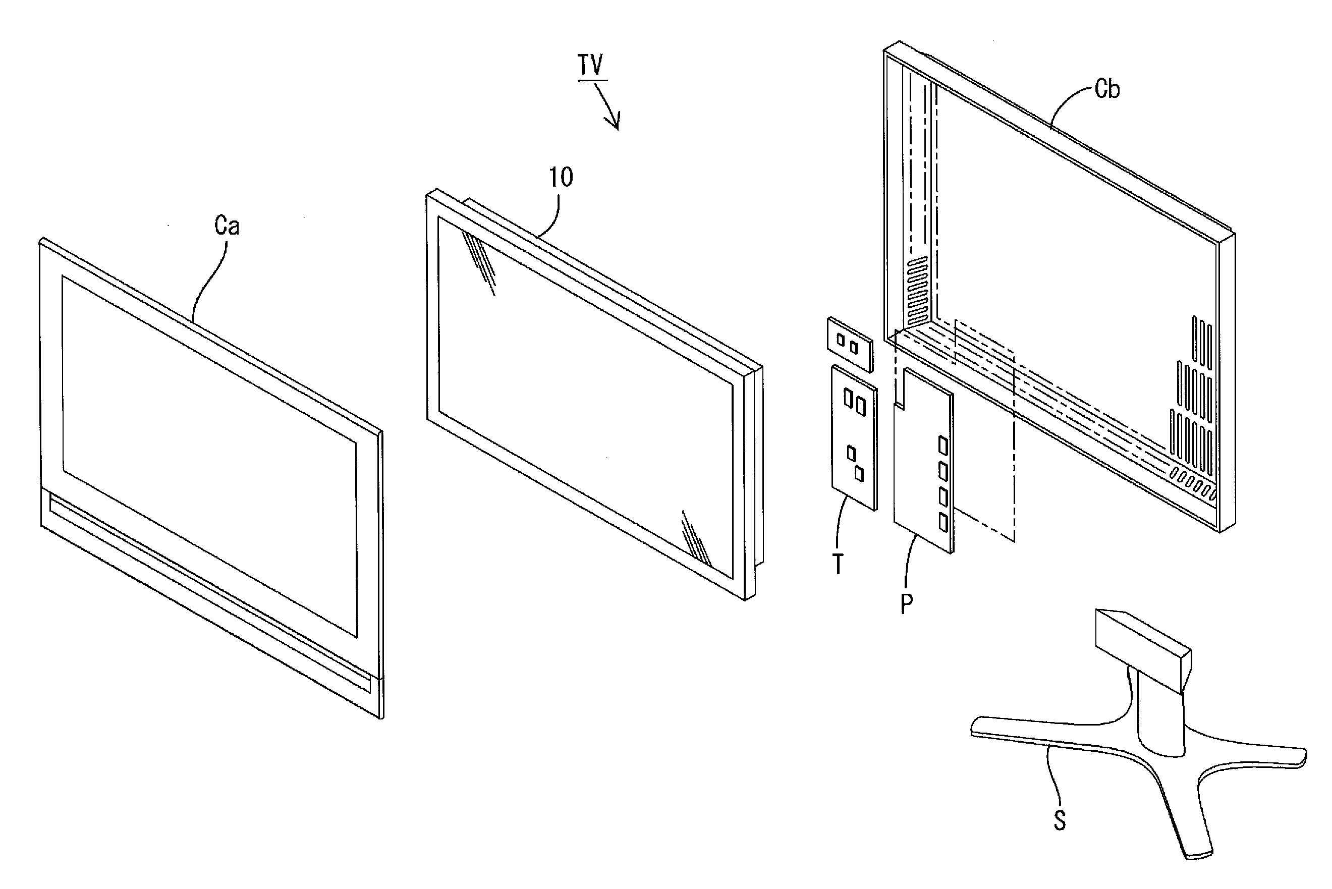
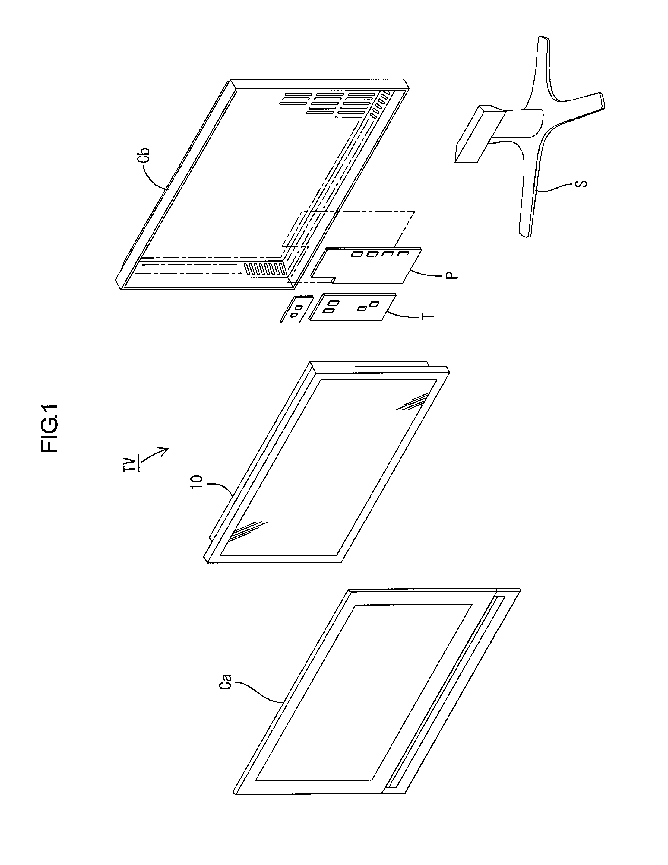
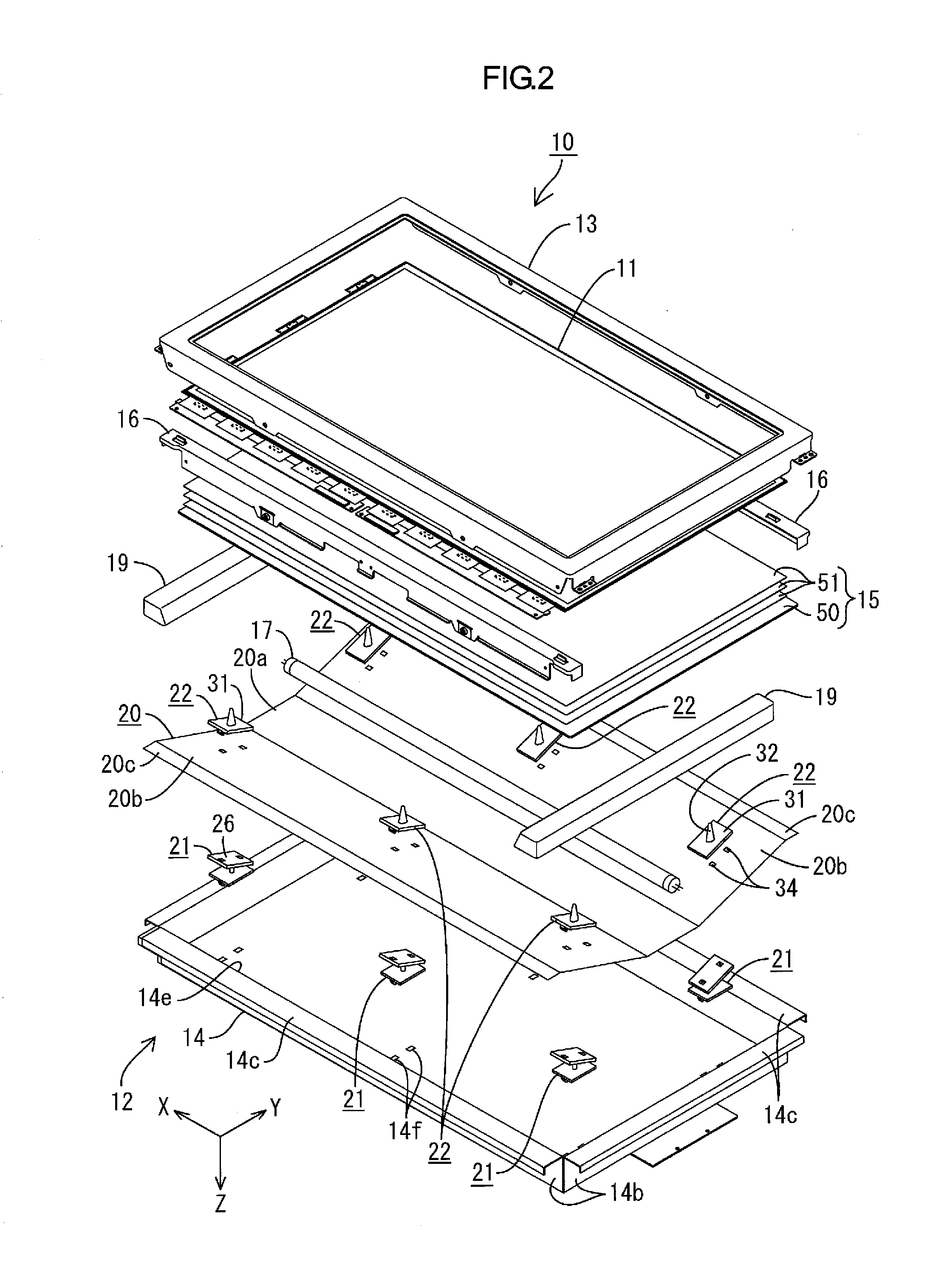
[0042]A first embodiment of the present invention will be described with reference to FIGS. 1 to 13. First, a configuration of a television receiver TV including a liquid crystal display device 10 will be described.

[0043]FIG. 1 is an exploded perspective view showing a schematic configuration of the television receiver of this embodiment. FIG. 2 is an exploded perspective view showing a schematic configuration of a liquid crystal display device included in the television receiver shown in FIG. 1. FIG. 3 is a sectional view showing a sectional configuration along the short-side direction of the liquid crystal display device shown in FIG. 2. FIG. 4 is a sectional view showing a sectional configuration along the long-side direction of the liquid crystal display device shown in FIG. 2. FIG. 5 is a plan view showing an arrangement configuration of a hot cathode tube and a second holding member (first holding member) of a chassis included in the liquid crystal display device shown in FIG....

first modified example

of the First Embodiment

[0116]A first modified example of the first embodiment will be described with reference to FIG. 14. This example illustrates a configuration in which the shape of each of a rising portion 20b-1, a receiving portion 26-1, and a pressing portion 31-1 is changed. FIG. 14 is an enlarged sectional view of a principal part of each of the holding members and the reflection sheet according to this modified example.

[0117]As shown in FIG. 14, the sectional shape taken along the Y-axis direction of the rising portion 20b-1 is a substantially arcuate shape which is a bow-like shape warped to the front side in a range from the rising proximal end to the rising distal end. That is, the rising portion 20b-1 has a form entirely projecting (swelling) toward the diffuser plate 50 side (light exit side) with respect to a line (chord) connecting the rising proximal end and the rising distal end. In other words, a space retained between the rising portion 20b-1 and the diffuser pl...

second modified example

of the First Embodiment

[0118]A second modified example of the first embodiment will be described with reference to FIG. 15. This example illustrates a configuration in which the shape of each of a rising portion 20b-2, a receiving portion 26-2, and a pressing portion 31-2 is changed. FIG. 15 is an enlarged sectional view of a principal part of each of the holding members and the reflection sheet according to this modified example.

[0119]As shown in FIG. 15, the sectional shape taken along the Y-axis direction of the rising portion 20b-2 is an inclined shape with respect to the bottom portion 20a. Specifically, the rising portion 20b-2 has a inclined shape (slope shape) with a constant slope (inclination angle) from the rising proximal end to the rising distal end, and the plate surface thereof is inclined with respect to each of the Y-axis direction (the plate surface of the bottom portion 20a) and the Z-axis direction. The inclination angle (an angle formed with respect to the Y-axi...


PUM

PropertyMeasurementUnit
sizeaaaaaaaaaa
angleaaaaaaaaaa
outer diameteraaaaaaaaaa

Abstract

Occurrence of uneven brightness in a backlight unit is suppressed. A backlight unit 12 includes a hot cathode tube 17 as a light source; a chassis 14 including a bottom plate 14a arranged on a side opposite to a light exit side with respect to the hot cathode tube 17 and housing the hot cathode tube 17; a reflection sheet 20 including a bottom portion 20a extending along the bottom plate 14a and a rising portion 20b rising from a bottom portion 20a to the light exit side and reflecting light; a first holding member 21 arranged on a side opposite to the light exit side with respect to each rising portion 20b and fixed to the chassis 14; and a second holding member 22 arranged on the light exit side of each rising portion 20b and configured to sandwich each rising portion 20b with the first holding member 21.

Description

TECHNICAL FIELD[0001]The present invention relates to a lighting device, a display device, and a television receiver.BACKGROUND ART[0002]A liquid crystal panel included in a liquid crystal display device, such as a liquid crystal television set, does not emit light, and thus a backlight unit is required as a separate lighting device. The backlight unit is arranged behind the liquid crystal panel (on a side opposite to a display surface side). The backlight unit includes a chassis having an opening on a liquid crystal panel side, a light source (such as a cold cathode tube) housed in the chassis, an optical member (such as a diffuser sheet) arranged at the opening of the chassis to effectively discharge light emitted from the light source toward the liquid crystal panel, and a reflection sheet laid in the chassis to reflect light emitted from the light source to the side of the optical member and the liquid crystal panel. Note that a backlight unit disclosed in the below-mentioned Pa...

Claims


Application Information

Patent Timeline
Patent Type & Authority Applications(United States)
IPC IPC(8): H04N3/14G09F13/14G02F1/13357F21V7/05
CPCG02F1/133605G02F2201/465G02F2201/46G02F1/133608
Inventor SHIMIZU, TAKAHARU
Owner SHARP KK
Why Eureka
Try Eureka