
Display device

a display device and display technology, applied in the field of display devices, can solve the problems of difficult to display black colors with favorable contrast, difficult to see images on the display,

Inactive Publication Date: 2012-07-12
SEMICON ENERGY LAB CO LTD
View PDF16 Cites 39 Cited by
  • Summary
  • Abstract
  • Description
  • Claims
  • Application Information

AI Technical Summary

Benefits of technology

The patent text describes a display device with a see-through capability that can display images on both sides. However, existing solutions have limitations in terms of display quality and the variety of display modes. The technical effect of the patent is to provide a display device with a light-modulating plate and shutters that can switch between a see-through mode and a light-blocking mode based on the use application or situation. This allows for a variety of display modes and improves the display quality and contrast.

Problems solved by technology

However, such a display device having a see-through capability has problems in that an image of the display can be peeked from the opposite side of the display and an image displayed on the display is difficult to see due to reflection of a scene on the opposite side of the display.
However, only by the light-modulating plate in which liquid crystal molecules are disordered by an interdigital comb electrode provided over the rear side of the display device having a see-through capability, there is a problem in that it is difficult to display black colors with favorable contrast when such a display device having a see-through capability is manufactured using a light-emitting element typified by an organic EL element.

Method used


Image

  • Display device
  • Display device
  • Display device

Examples


embodiment 1

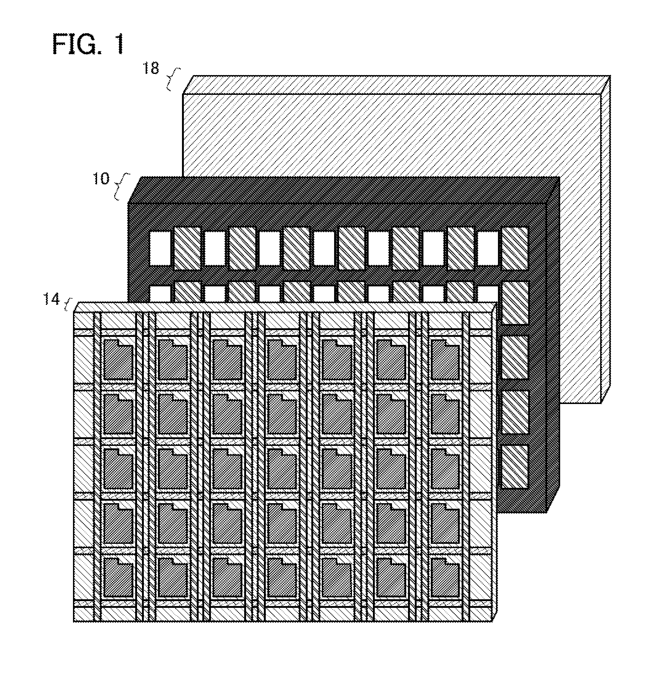
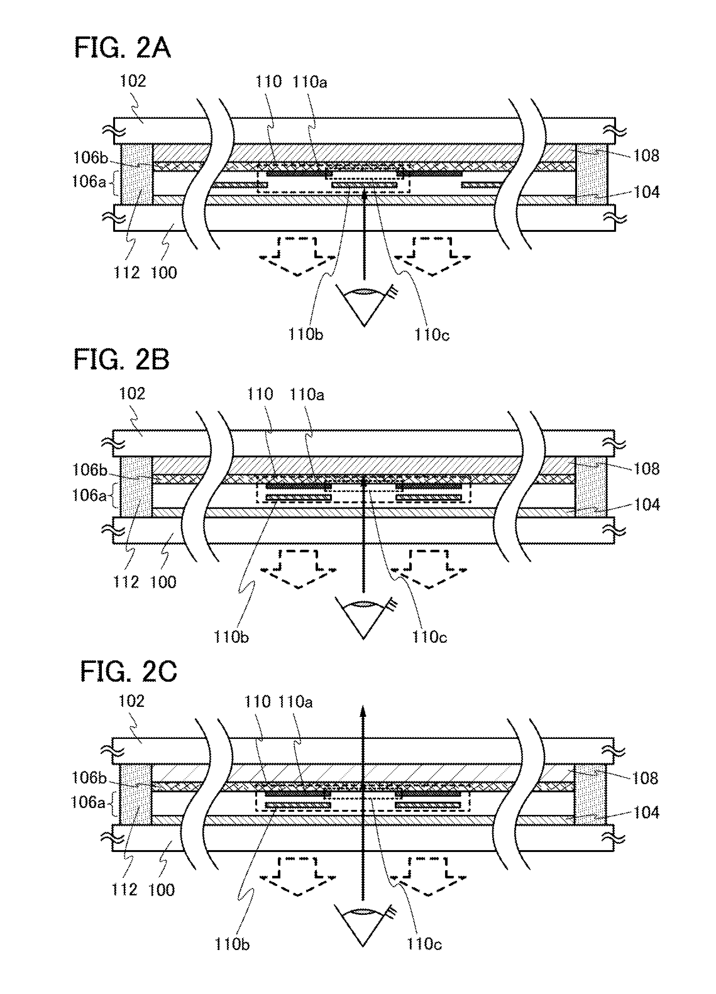
[0037]In this embodiment, a display device having a see-through capability according to one embodiment of the disclosed invention will be described with reference to FIG. 1, FIGS. 2A to 2C, and FIGS. 3A-1, 3A-2, 3B-1, 3B-2, 3C-1, 3C-2, and 3D-1, 3D-2.

[0038]FIG. 1 is an oblique drawing schematically illustrating a structure of a display device having a see-through capability according to one embodiment of the disclosed invention. The display device illustrated in FIG. 1 includes a first display portion 14 having pixels including dual-emission type light-emitting elements, a second display portion 18 having a light-scattering liquid crystal layer, and a shutter-shaped light-blocking unit 10 between the first display portion 14 and the second display portion 18. The first display portion 14 has a light-transmitting property at least when the dual-emission type light-emitting element is in a non-light-emission state, while the second display portion 18 has a light-transmitting property ...

embodiment 2

[0100]In this embodiment, a display device having a different mode from that of the display device having a see-through capability described in Embodiment 1 will be described with reference to FIG. 4.

[0101]The display device illustrated in FIG. 4 includes the first support having a light-transmitting property 100, the first display portion 104 having light-emitting elements provided for the first support 100, the second support having a light-transmitting property 102 provided opposite to the first support 100, the second display portion 108 having a light-scattering liquid crystal layer and being provided over the second support 102 so as to be opposite to the first display portion 104, and the MEMS structure portion 106a and the MEMS driving element portion 106b provided between the first display portion 104 and the second support 102. The MEMS structure portion 106a has the shutter 110 that includes the light-blocking layer 110a provided with the opening portion 110c and the mova...

embodiment 3

[0108]In this embodiment, a display device having a different mode from that of the display device having a see-through capability described in Embodiment 1 will be described with reference to FIG. 5A and FIG. 5B.

[0109]FIG. 5A and FIG. 5B are each a cross-sectional view of a display device in accordance with one embodiment of the disclosed invention. FIG. 5A illustrates a display mode in which images are displayed on both surfaces (double-sided display mode), while FIG. 5B illustrates a display mode in which the first display portion 104 is used as a backlight.

[0110]A structure of the display device illustrated in FIG. 5A and FIG. 5B is described. The display device illustrated in FIG. 5A and FIG. 5B includes the first support having a light-transmitting property 100, the first display portion 104 having light-emitting elements provided for the first support 100, the second support having a light-transmitting property 102 provided opposite to the first support 100, a second display ...


PUM

PropertyMeasurementUnit
thicknessaaaaaaaaaa
thicknessaaaaaaaaaa
thicknessaaaaaaaaaa

Abstract

A display device having a light-emitting element and a see-through capability, with which a variety of display modes can be exhibited depending on a use application or situation. In such a display device having a see-through capability, between a first display portion having pixels including dual-emission type light-emitting elements and a second display portion having a light-scattering liquid crystal layer, a shutter-shaped light-blocking unit is provided so that a variety of display modes can be exhibited depending on use applications or situations by selecting modes of the first display portion, the second display portion, and the shutter-shaped light-blocking unit.

Description

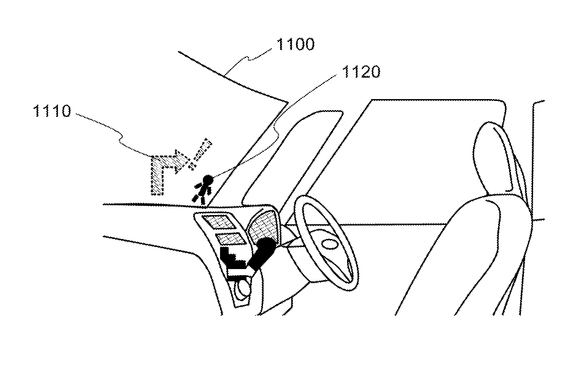
BACKGROUND OF THE INVENTION[0001]1. Field of the Invention[0002]One embodiment of the present invention relates to display devices using light-emitting elements. In particular, one embodiment of the present invention relates to display devices having see-through capabilities and using light-emitting elements.[0003]2. Description of the Related Art[0004]In recent years, displays having see-through capabilities with which the opposite side of a display can be seen have been attracting attentions. Application fields of such displays having see-through capabilities are windshields on vehicles, windows of architectural structures such as houses and buildings, showcases and store windows of department stores, and the like.[0005]With use of displays having see-through capabilities, a user can see an object while information on the object on the other side of a display is displayed on the display, or an object on the other side of a display can be decorated with an image for decoration disp...

Claims


Application Information

Patent Timeline
Patent Type & Authority Applications(United States)
IPC IPC(8): G02F1/1334G02F1/1333
CPCG02F1/1334G02B2027/012G02B27/01G02F1/1333B65H23/032B65H20/00F16C11/0671B65H2403/52B65H2402/51G02F1/133603
Inventor YAMAZAKI, SHUNPEIHIRAKATA, YOSHIHARU
Owner SEMICON ENERGY LAB CO LTD
Learn More