Near field communication device and method of controlling the same
a technology of near field communication and communication device, which is applied in the direction of devices with near field communication, high-level techniques, instruments, etc., can solve the problems of low interference, network difficulty in being connected to a network, and various devices (apparatuses) such as air conditioners and microwaves, so as to save energy
- Summary
- Abstract
- Description
- Claims
- Application Information
AI Technical Summary
Benefits of technology
Problems solved by technology
Method used
Image

Examples
embodiment 1
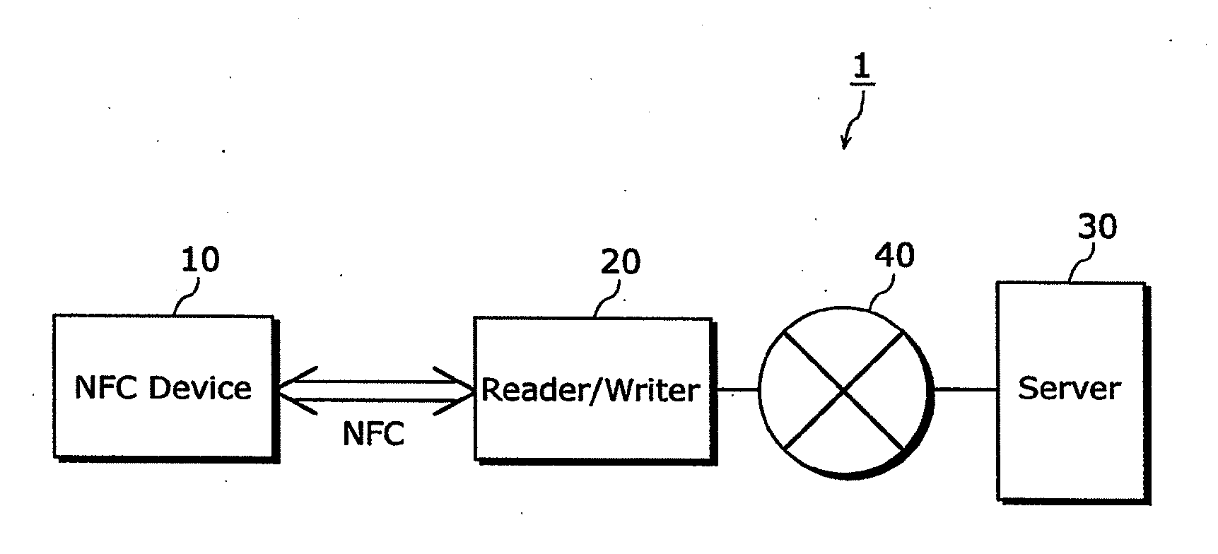
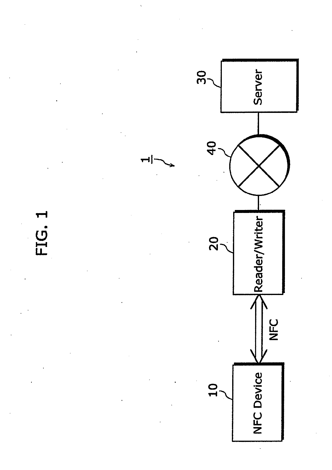
[0056]FIG. 1 is a diagram showing an example of a configuration of a system including an NFC device according to embodiments of the present invention. The system shown in FIG. 1 includes an NFC device 10, a reader / writer 20, and a server 30.
[0057]Likewise a mobile phone, the reader / writer 20 has an NFC function and a function of connecting the reader / writer 20 to the Internet 40.
[0058]Examples of the NFC device 10 are an air conditioner, a microwave, and the like. The NFC device 10 has the NFC function but does not have a function of connecting the NFC device 10 to the Internet 40.
[0059]The server 30 is on the Internet 40. The server 30 has a database in which information regarding the NFC device 10 is stored.
[0060]In the system 1 having the above-described configuration, the reader / writer 20 receives information such as a type or model of the NFC device 10 by using NFC, thereby obtains corresponding information such as a manual of the NFC device 10 from the server 30, and then disp...
embodiment 2
[0105]In Embodiment 2, description is given for another example of the structure of the NFC device 100 according to Embodiment 1.
[0106]FIG. 6 is a block diagram showing an example of a structure of the NFC device according to Embodiment 2. Here, the same reference numerals of FIG. 2 are assigned to the identical units of FIG. 6, so that the identical units are not explained in detail again below.
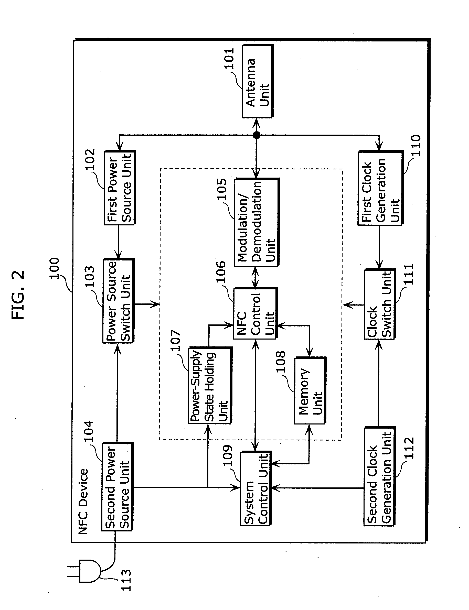
[0107]The NFC device 200 shown in FIG. 6 includes the antenna unit 101, the first power source unit 102, the power source switch unit 103, the second power source unit 104, the modulation / demodulation unit 105, the NFC control unit 106, the memory unit 108, the first clock generation unit 110, the clock switch unit 111, the second clock generation unit 112, a power-supply state holding unit 207, a system control unit 209, and a capacitor unit 213. The NFC device 200 is generally connected to the plug 113, for example, and receives power via the plug 113.
[0108]The NFC device 200 shown in FIG....
embodiment 3
[0130]In Embodiment 3, description is given for another example of the structure of the NFC device 200 according to Embodiment 2.
[0131]FIG. 8 is a block diagram showing an example of a structure of an NFC device according to Embodiment 3. Here, the same reference numerals of FIG. 6 are assigned to the identical units of FIG. 8, so that the identical units are not explained again below.
[0132]The NFC device 300 shown in FIG. 8 includes the antenna unit 101, the first power source unit 102, the power source switch unit 103, the second power source unit 104, the modulation / demodulation unit 105, the NFC control unit 106, the memory unit 108, the first clock generation unit 110, the clock switch unit 111, the second clock generation unit 112, the power-supply state holding unit 207, the system control unit 209, the capacitor unit 213, and a system activation unit 314. The NFC device 300 is generally connected to the plug 113, for example, and receives power via the plug 113.
[0133]The NFC...
PUM
 Abstract
Description
Claims
Application Information
 - R&D
- Intellectual Property
- Life Sciences
- Materials
- Tech Scout
- Unparalleled Data Quality
- Higher Quality Content
- 60% Fewer Hallucinations
Browse by: Latest US Patents, China's latest patents, Technical Efficacy Thesaurus, Application Domain, Technology Topic, Popular Technical Reports.
© 2025 PatSnap. All rights reserved.Legal|Privacy policy|Modern Slavery Act Transparency Statement|Sitemap|About US| Contact US: help@patsnap.com