System for Pushing and Pulling Surgical Implants into Position in Vivo Via a Tether

a surgical implant and tethering technology, applied in the field of surgical implants, can solve the problems of increasing the possibility of pathway divergence and/or reducing the risk of causing damage to neural structures or bony obstructions, and reducing the risk of causing damage to neural and vascular structures. , to achieve the effect of reducing post-operative pain, reducing soft tissue damage, and shortening surgery

Active Publication Date: 2012-07-12
NUVASIVE
View PDF1 Cites 16 Cited by
  • Summary
  • Abstract
  • Description
  • Claims
  • Application Information

AI Technical Summary

Benefits of technology

[0018]Accordingly, it is an objective of the instant invention to provide a system that minimizes soft tissue damage and provides less post-operative pain.
[0019]It is a further objective of the instant invention to provide a targeting system that permits percutaneous positioning of a biocompatible device at multiple vertebral levels of greater than three.
[0020]It is yet another objective of the instant invention to provide a targeting system that can percutaneously treat scoliosis patients.
[0021]It is a still further objective of the invention to teach a targeting system which allows for shorter surgery, decreased x-ray exposure, and fewer complications for the patient.
[0022]It is a further objective of the instant invention to provide a targeting system that is simple to operate to reduce the training the surgeon must undergo for operation of peripheral systems.

Problems solved by technology

Although there are numerous patents directed to systems and methods for insertion of a stabilizing implant at a selected area of an anatomy, the prior art nevertheless fails to teach a targeting system for the insertion of an implant using minimally invasive techniques having a decreased risk of causing damage to neural structures or bony obstructions using minimal, if any, radiation exposure to the patient and / or surgeon.
This increases the possibility of pathway divergence and / or damage to neural and vascular structures.
Moreover, none of the aforementioned references provide audible and / or tactile feedback to the surgeon that indicates the target area has been reached.

Method used


Image

  • System for Pushing and Pulling Surgical Implants into Position in Vivo Via a Tether
  • System for Pushing and Pulling Surgical Implants into Position in Vivo Via a Tether
  • System for Pushing and Pulling Surgical Implants into Position in Vivo Via a Tether

Examples


Embodiment Construction

[0056]While the present invention is susceptible of embodiment in various forms, there is shown in the drawings and will hereinafter be described a presently preferred, albeit not limiting, embodiment with the understanding that the present disclosure is to be considered an exemplification of the present invention and is not intended to limit the invention to the specific embodiments illustrated.

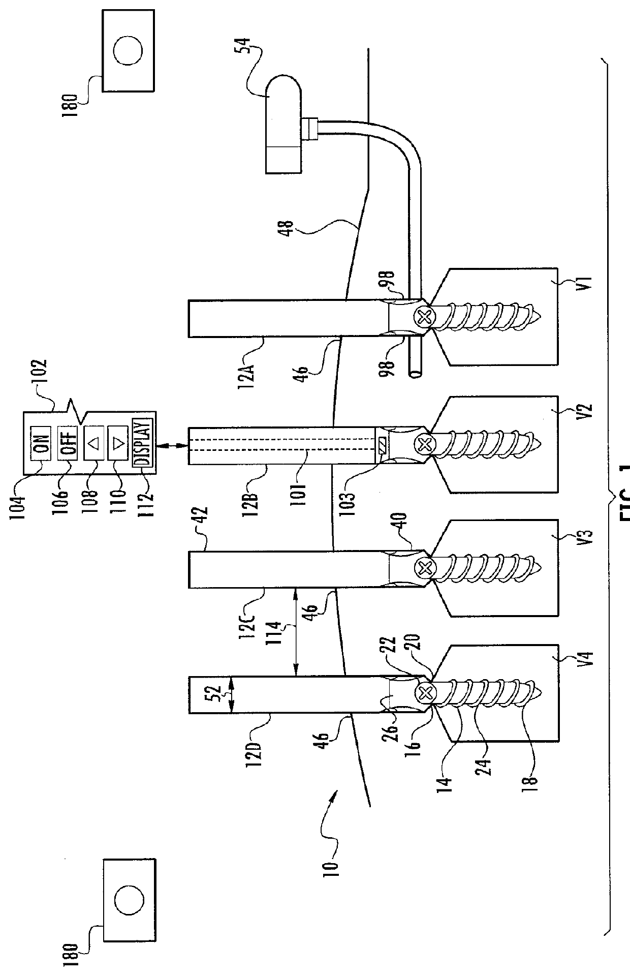
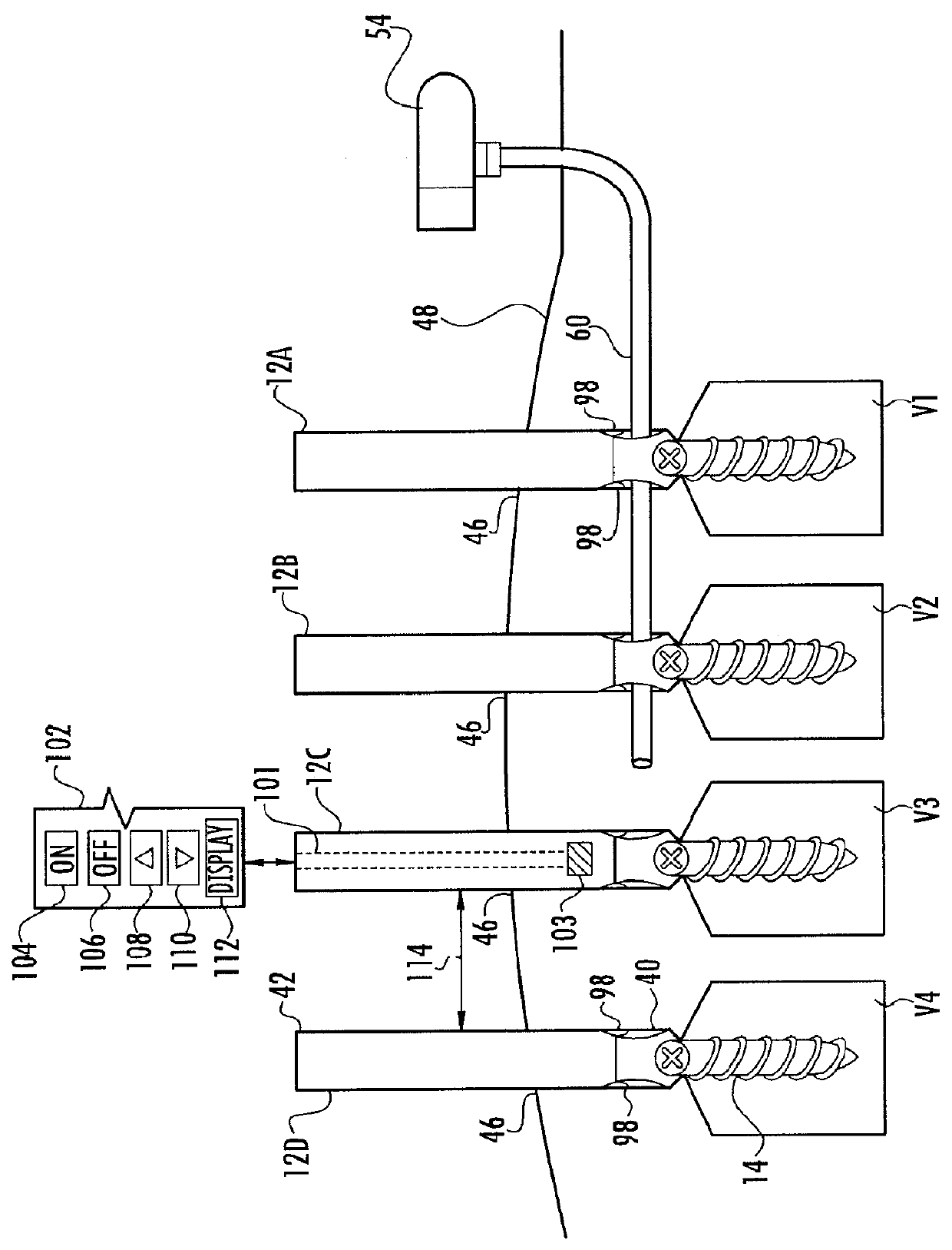
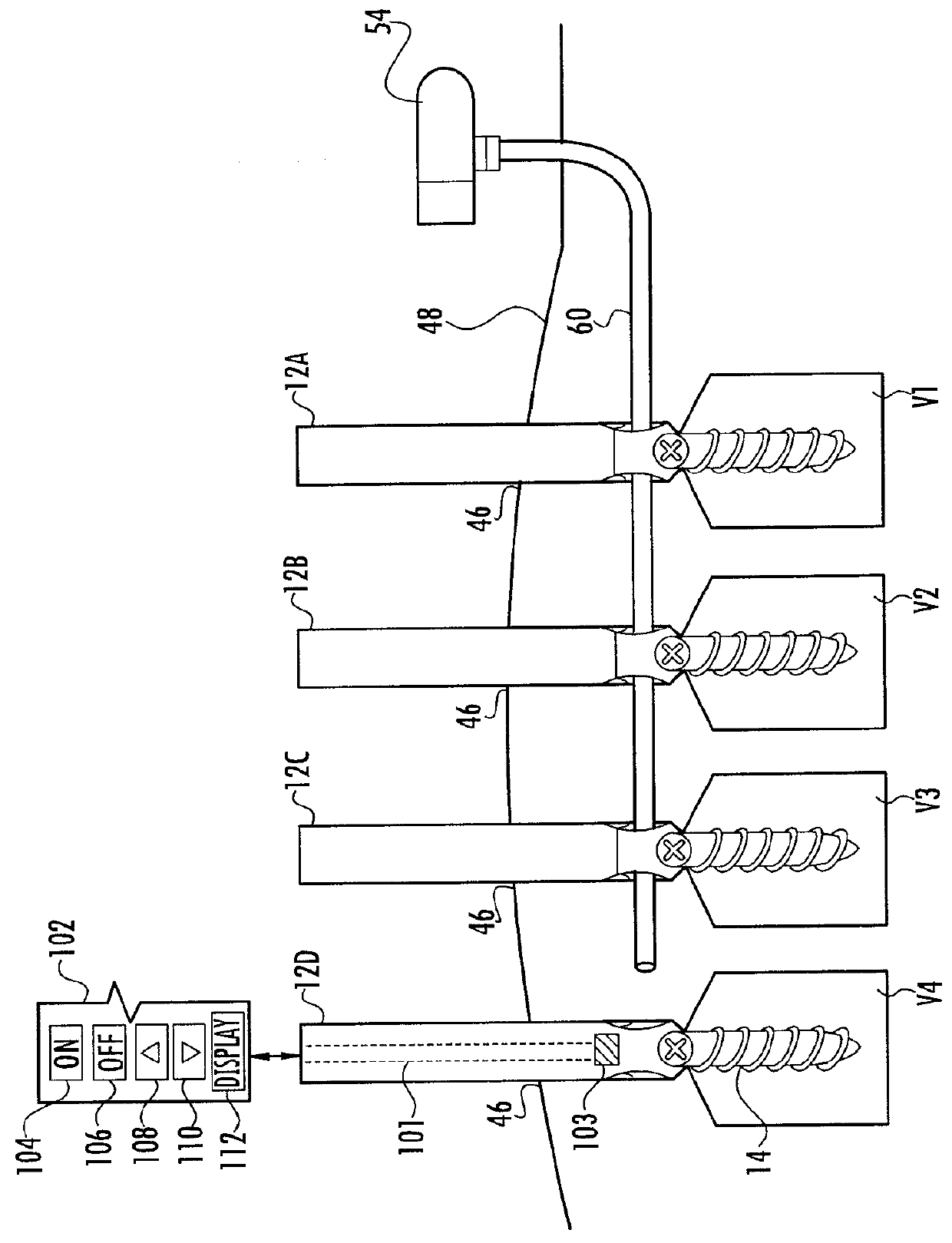
[0057]Referring to FIGS. 1-8 which illustrate the system 10 of the present invention which is suitable for pulling and / or pushing implants in vivo via a tether, wherein like elements are numbered consistently throughout. FIG. 1 shows a plurality of extenders 12A, 12B, 12C, 12D, and collectively 12. The extenders 12 are shown having a generally tube or cylindrical shape, but may take on other forms. A plurality of anchoring members 14 (also referred to as fastening means) are used to secure the extenders 12 to one or more parts of a human body. The anchoring members 14 are depicted here as mu...


PUM


Abstract

The present invention describes a system suitable for guiding a biocompatible device to a target area within the body (in vivo) and method of using the same. The system includes a targeting member being constructed of, or having a steering material, which can be coupled to a biocompatible device. The system further includes one or more devices which are used to maneuver the targeting member into position prior to attachment of the biocompatible device. The biocompatible device is traversed into position through the passageway created by the targeting member and secured to one or more anchoring members.

Description

CROSS REFERENCE TO RELATED APPLICATIONS[0001]This application is a continuation-in-part of U.S. application Ser. No. 13 / 313,528, filed Dec. 7, 2011, entitled “Method and Apparatus for Facilitating Navigation of an Implant”, which is a continuation of U.S. application Ser. No. 12 / 728,818, filed on Mar. 22, 2010, entitled “Method and Apparatus For Facilitating Navigation of An Implant”, which is a continuation-in-part of U.S. application Ser. No. 12 / 157,397, filed on Jun. 10, 2008, entitled “Magnetic Targeting System for Facilitating Navigation”, which is now issued U.S. Pat. No. 7,976,546, on Jun. 22, 2011, which is a continuation-in-part of U.S. application Ser. No. 13 / 151,756, filed on Jun. 2, 2011, entitled “Magnetic Targeting System For Facilitating Navigation”, which is a continuation-in-part of U.S. application Ser. No. 11 / 462,592 filed on Aug. 4, 2006, entitled “Magnetic Targeting System and Method of Using The Same”, which is a continuation-in-part of U.S. application Ser. No...

Claims


Application Information

Patent Timeline
Patent Type & Authority Applications(United States)
IPC IPC(8): A61B17/56
CPCA61B17/7002A61B17/7083A61B17/7085A61B2019/2253A61B2017/003A61B2017/00876A61B19/22A61B34/73A61B34/70
Inventor GEIST, WYATT DRAKEWALSH, CHRISTOPHER
Owner NUVASIVE
Why Eureka
Try Eureka