
System and method for variable-size table construction applied to a table-lookup approach for load-spreading in forwarding data in a network

Active Publication Date: 2012-07-12
TELEFON AB LM ERICSSON (PUBL)
View PDF7 Cites 18 Cited by
  • Summary
  • Abstract
  • Description
  • Claims
  • Application Information

AI Technical Summary

Benefits of technology

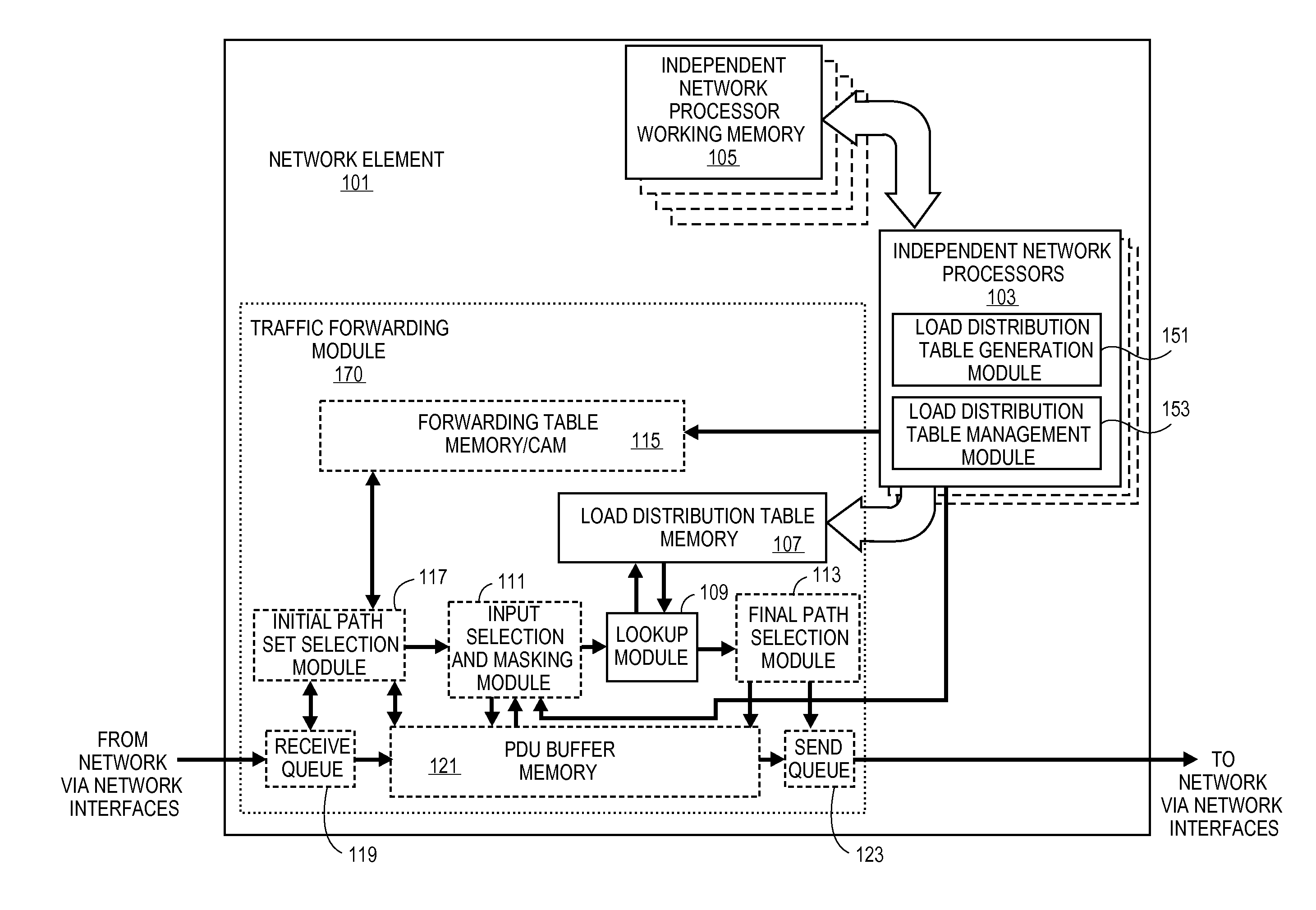
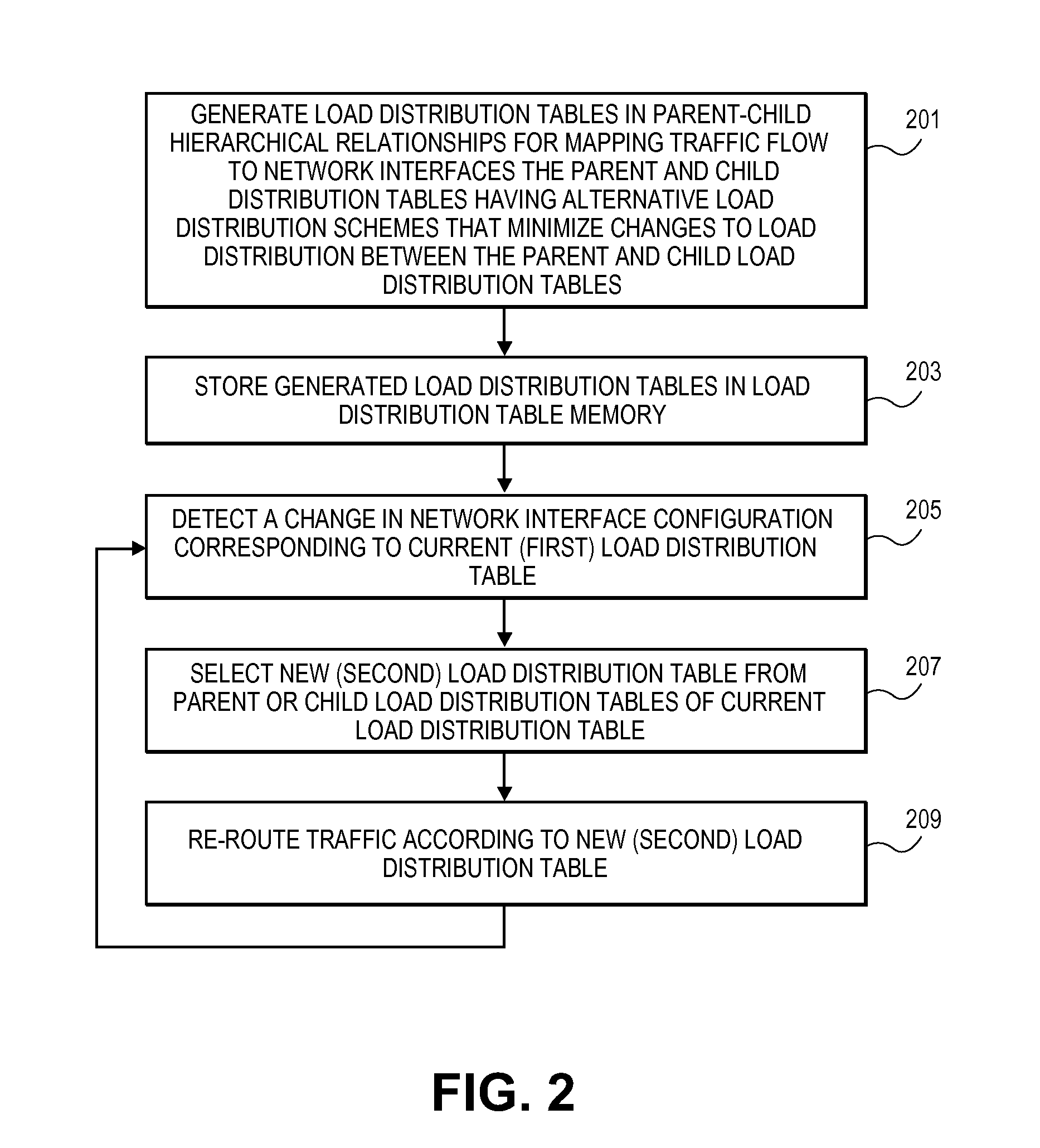
[0007]A method in accordance with embodiments of the present invention is implemented in a network element in a network; the network element manages load distribution across a plurality of network interfaces of the network. The network element redirects traffic flow directed toward the plurality of network interfaces in response to changes in configuration of the plurality of network interfaces, where each traffic flow is a set of protocol data units (PDUs), having an ordered delivery requirement, that are transmitted across the network between a source node and a destination node. The method comprises the steps of generating, by a processor in the network element, a set of load distribution tables having a hierarchical relationship for mapping a traffic flow to a plurality of equal cost paths. The hierarchical relationship defining a child or parent relation for each load distribution table with another load distribution table in the set of load distribution tables, where a child load distribution table and a corresponding parent load distribution table in the set of load distribution tables provide alternate load distribution schemes for the traffic flow across the plurality of network interfaces relative to one another. The alternative load distribution schemes minimize changes to an initial load distribution scheme of the corresponding child load distribution table or parent load distribution table storing the generated set of load distribution tables in a load distribution table memory unit. The method also includes detecting, by the network element, a change in the configuration of the plurality of network interfaces corresponding to a first load distribution table from the set of load distribution tables, selecting a second load distribution table from among child load distribution tables or parent load distribution tables of the first load distribution table. The second load distribution table provides an alternative load distribution scheme to distribute traffic flow directed toward the plurality of network interfaces that minimizes changes to an initial load distribution scheme of the first load distribution table for the traffic flow. The network element reroutes the traffic flow in accordance with the alternative load distribution scheme of the second load distribution table while minimizing changes to the load distribution scheme of the first load distribution table for the traffic flow.
[0008]In accordance with embodiments of the present invention, a network element is disposed in a network, the network element manages load distribution across a plurality of network interfaces of the network. The network element redirects traffic flow directed toward the plurality of network interfaces in response to changes in configuration of the plurality of network interfaces, where each traffic flow is a set of protocol data units (PDUs) having an ordered delivery requirement. The PDUs are transmitted across the network between a source node and a destination node. The network element comprises a traffic forwarding module to forward each traffic flow toward the destination node according to a set of load distribution tables. The traffic forwarding module includes a load distribution table memory unit to store the set of load distribution tables and a network processor coupled to the traffic forwarding module. The network processor executes a load distribution table generating module and a load distribution table management module. The load distribution table generating module generates the set of load distribution tables. The load distribution tables have a hierarchical relationship for mapping a traffic flow to a plurality of equal cost paths. The hierarchical relationship defines a child or parent relation for each load distribution table with another load distribution table in the set of load distribution tables, where a child load distribution table and a corresponding parent load distribution table in the set of load distribution tables provide alternate load distribution schemes for the traffic flow across the plurality of network interfaces relative to one another. The alternative load distribution schemes minimize changes to an initial load distribution scheme of the corresponding child load distribution table or parent load distribution table. The load distribution table management module detects a change in a configuration of the plurality of network interfaces corresponding to a first load distribution table from the set of load distribution tables and selects a second load distribution table from among child load distribution tables or parent load distribution tables of the first load distribution table. The second load distribution table provides an alternative load distribution scheme to distribute traffic flow directed toward the plurality of network interfaces that minimizes changes to an initial load distribution scheme of the first load distribution table for the traffic flow.

Problems solved by technology

However, in some implementations ECMP can have limitations in supporting operation, administration and management (OAM) functions and difficulties in evenly spreading a traffic load in asymmetrical topologies.
ECMP and similar hashing-based techniques have limitations in that in any irregular network or in any regular network that is in a failure scenario these techniques have difficulties with distributing the load evenly across the plurality of equal cost paths.
The hashing scheme is typically not changed dynamically in a network failure scenario due to the disruption that would be caused, as a result the hashing scheme selected may not produce substantially even load distribution in the changed network topology.

Method used


Image

  • System and method for variable-size table construction applied to a table-lookup approach for load-spreading in forwarding data in a network
  • System and method for variable-size table construction applied to a table-lookup approach for load-spreading in forwarding data in a network
  • System and method for variable-size table construction applied to a table-lookup approach for load-spreading in forwarding data in a network

Examples


Embodiment Construction

[0017]In the following description, numerous specific details are set forth. However, it is understood that embodiments of the invention may be practiced without these specific details. In other instances, well-known circuits, structures and techniques have not been shown in detail in order not to obscure the understanding of this description. It will be appreciated, however, by one skilled in the art, that the invention may be practiced without such specific details. Those of ordinary skill in the art, with the included descriptions, will be able to implement appropriate functionality without undue experimentation.

[0018]The operations of the various flow charts as illustrated in the figures will be described with reference to the exemplary embodiments illustrated in the various diagrams as provided by figures. However, it should be understood that the operations of the flow charts can be performed by embodiments of the invention other than those discussed with reference to the diag...


PUM


Abstract

A network element disposed in a network, where the network element implements a process to manage load distribution across a plurality of network interfaces of the network. The network element redirects traffic flow directed toward the plurality of network interfaces in response to changes in configuration of the plurality of network interfaces, where each traffic flow is a set of protocol data units (PDUs), having an ordered delivery requirement, and where the PDUs are transmitted across the network between a source node and a destination node. The redirection process minimizes data traffic flow disruption when the load distribution is determined using a set of load distribution tables instead of a hashing algorithm.

Description

CROSS-REFERENCE TO RELATED APPLICATIONS[0001]The present application claims the benefit under 35 U.S.C. §119 to U.S. Provisional Application Ser. No. 61 / 431,250, filed on Jan. 10, 2011, and U.S. Provisional Patent Application Ser. No. 61 / 487,124, filed on May 17, 2011. The foregoing applications, along with U.S. patent application Ser. No. 13 / 091,066, filed on Apr. 20, 2011, U.S. patent application Ser. No. 13 / 097,336, filed on Apr. 29, 2011, U.S. patent application Ser. No. 12 / 877,830, filed on Sep. 8, 2010, and U.S. patent application Ser. No. 12 / 877,826, filed on Sep. 8, 2010, are hereby incorporated by reference into the present application in their entirety for all purposes.FIELD OF THE INVENTION[0002]The embodiments of the invention relate to a method and system for improving load distribution in a network. Specifically, the embodiments of the invention relate to the improved use of a load distribution table populated with next hop discriminators to diminish disruption to data...

Claims


Application Information

Patent Timeline
IPC IPC(8): G06F15/173
CPCH04L45/245H04L47/125H04L45/38Y02D30/50
Inventor ALLAN, DAVID IANGRAY, ERIC WARDHALPERN, JOELMANSFIELD, SCOTT ANDREW
Owner TELEFON AB LM ERICSSON (PUBL)
Learn More