
Support for solar energy collectors

a technology for solar energy collectors and bearing mounts, applied in the direction of heat collector mounting/supports, pv power plants, light and heating equipment, etc., can solve the problems of high cost of customizing bearing mounts, large amount of additional labor, and misalignment of piles, so as to reduce the cost of constructing solar collection systems

Active Publication Date: 2012-07-19
SUNPOWER CORPORATION
View PDF12 Cites 161 Cited by
  • Summary
  • Abstract
  • Description
  • Claims
  • Application Information

AI Technical Summary

Benefits of technology

[0007]An aspect of at least one of the inventions disclosed herein includes the realization that costs for constructing solar collection systems can be reduced by accommodating misalignments and certain structural components used for supporting the collectors. For example, in the solar collection systems which incorporate an extended drive shaft or torque tube that is supported above the ground and pivoted through a range of motion, the torque tube is supported by piles that can be mounted to the earth using various techniques such as cementing, driving, screwing (e.g., with helical piles, earth screws, etc.). During the initial construction phase of such a system, these piles or pillars are carefully aligned prior to the final installation step, i.e., pouring cement.

Problems solved by technology

However, events can occur to cause misalignments in the piles.
When such a misalignment occurs, substantial amounts of additional labor may be required to prepare a properly aligned and suitable surface for mounting bearing supporting the torque tube.
Because these installations are always outside and can be in remote locations, the costs for customizing such a bearing mount can be high.

Method used


Image

  • Support for solar energy collectors
  • Support for solar energy collectors
  • Support for solar energy collectors

Examples


Embodiment Construction

[0034]The following detailed description is merely illustrative in nature and is not intended to limit the embodiments of the subject matter or the application and uses of such embodiments. As used herein, the word “exemplary” means “serving as an example, instance, or illustration.” Any implementation described herein as exemplary is not necessarily to be construed as preferred or advantageous over other implementations. Furthermore, there is no intention to be bound by any expressed or implied theory presented in the proceeding technical field, background, brief summary, or the following detailed description.

[0035]“Coupled”—The following description refers to elements or nodes or features being “coupled” together. As used herein, unless expressly stated otherwise, “coupled” means that one element / node / feature is directly or indirectly joined to (or directly or indirectly communicates with) another element / node / feature.

[0036]“Locating connector”—The following description refers to ...


PUM


Abstract

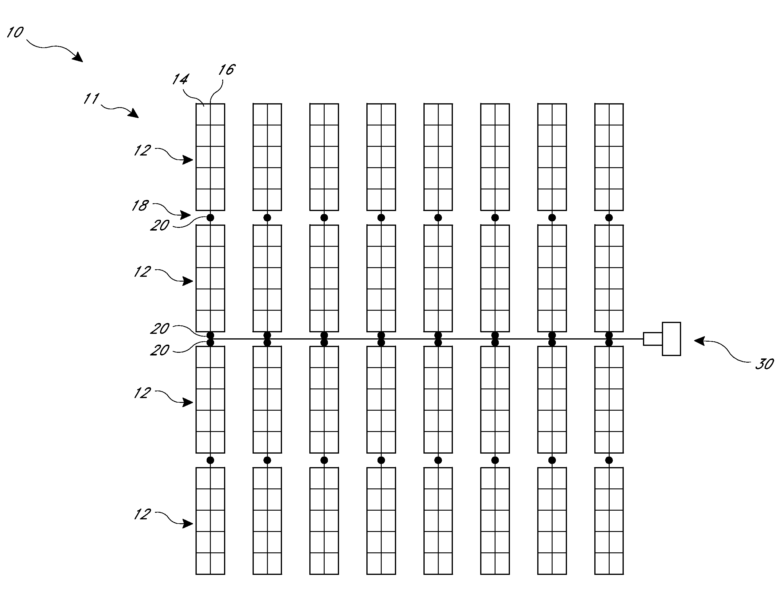
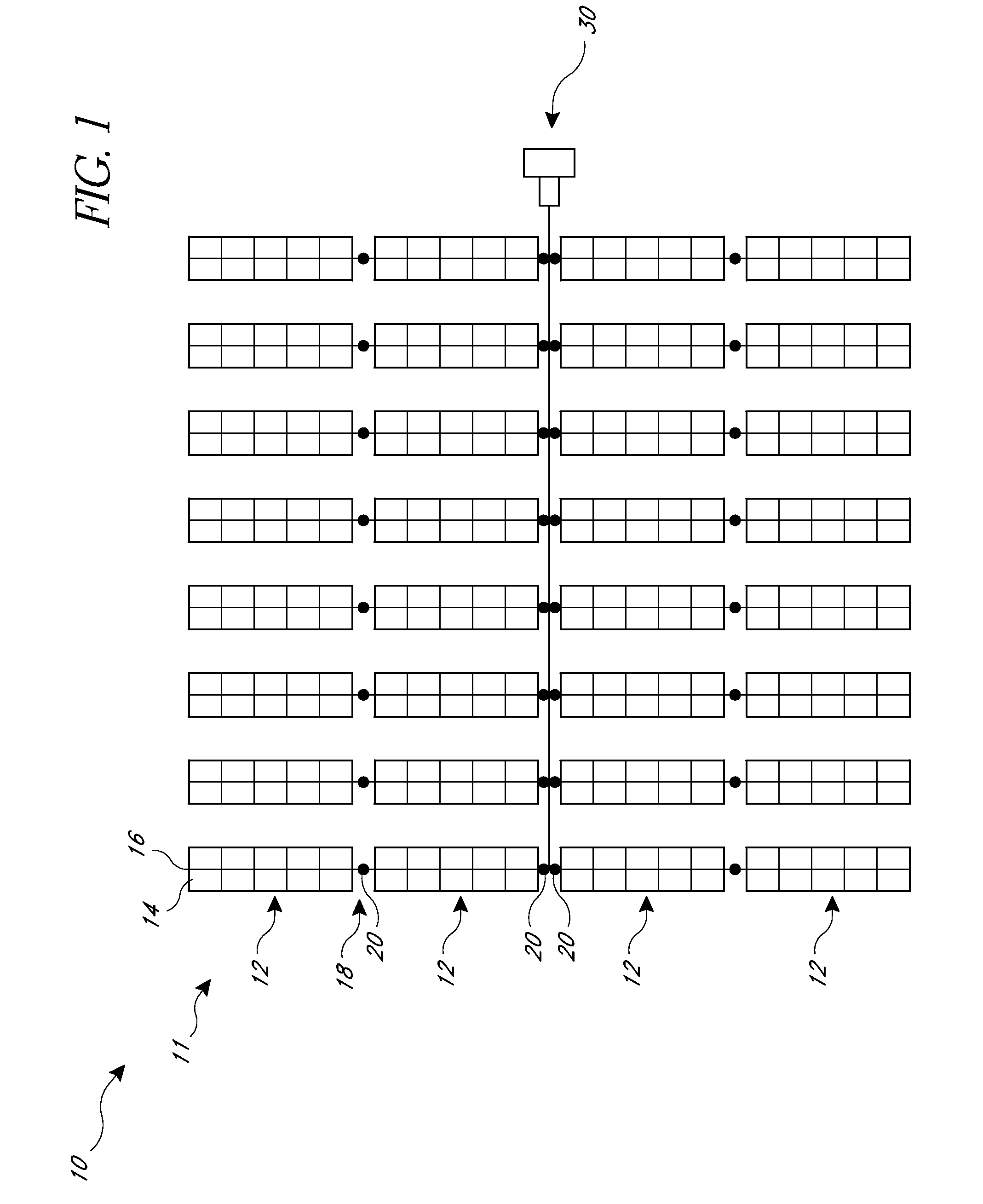
A solar energy collection system can include support devices configured to accommodate misalignment of components during assembly. For example, the system can include piles fixed to the earth and an adjustable bearing assembly at the upper end of the pile. The adjustable bearing assembly can include at least one of a vertical adjustment device, a lateral adjustment device and an angular adjustment device. The solar energy collection system can also include a plurality of solar energy collection device pre-wired together and mounted to a support member so as to form modular units. The system can also include enhanced supports for wire trays extending between rows of solar energy collection devices.

Description

RELATED APPLICATIONS[0001]The present application claims priority to U.S. Provisional Patent Application Nos. 61 / 437,509 filed Jan. 28, 2011 and 61 / 433,141 filed on Jan. 14, 2011.STATEMENT REGARDING FEDERALLY SPONSORED RESEARCH OR DEVELOPMENT[0002]The inventions described herein were made with Governmental support under contract number DE-FC36-07GO17043 awarded by the United States Department of Energy. The Government may have certain rights in the inventions disclosed.TECHNICAL FIELD[0003]Embodiments of the subject matter described herein relate generally to solar energy systems which include supports for solar energy collecting devices.BACKGROUND[0004]Larger solar collector installations usually include an array of solar collector assemblies. Such systems can be used in conjunction with photovoltaic panels, thermal solar collector devices as well as concentrators for concentrating solar energy onto photovoltaic devices or thermal solar collection devices.[0005]Some of these solar ...

Claims


Application Information

Patent Timeline
Patent Type & Authority Applications(United States)
IPC IPC(8): H01L31/052F24S23/00F24S50/20
CPCF24J2/523F24J2/541Y02E10/47F24J2002/5489F24J2002/5468Y02E10/52F24S25/10F24S30/425F24S2030/136F24S2030/17H02S20/20H02S30/10H02S30/20H02S40/36
Inventor COLE, COREYARDELL-SMITH, ZACHARYCIASULLI, JOHNJENSEN, SOREN
Owner SUNPOWER CORPORATION
Learn More