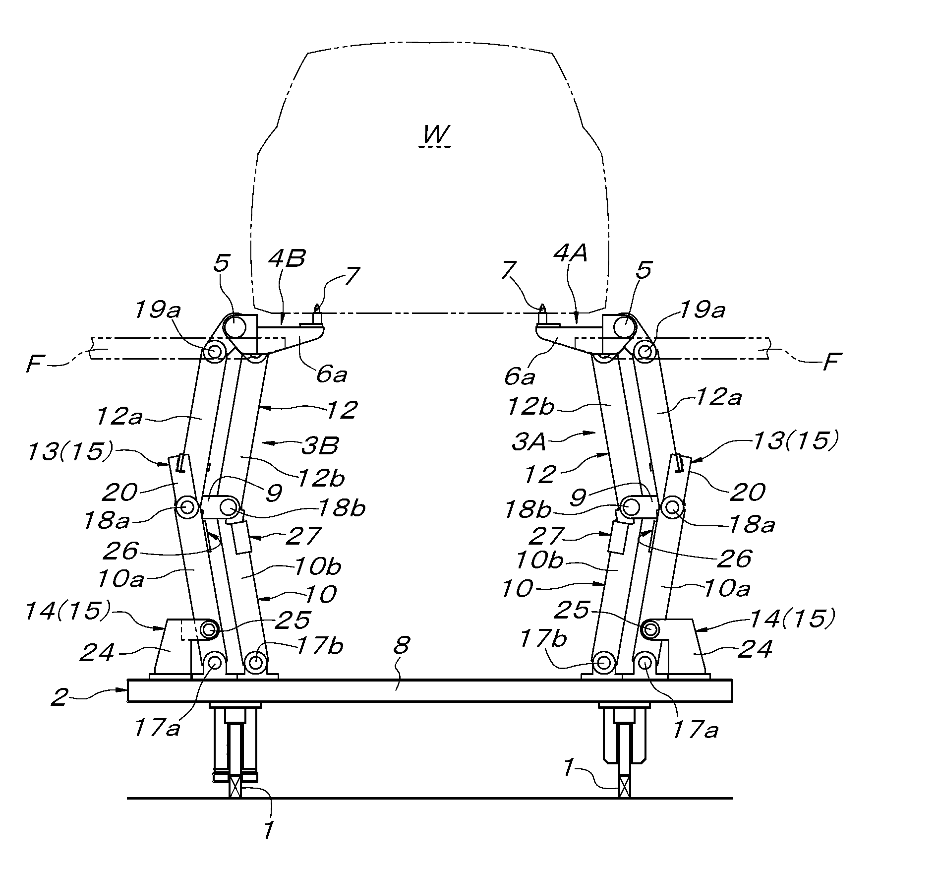
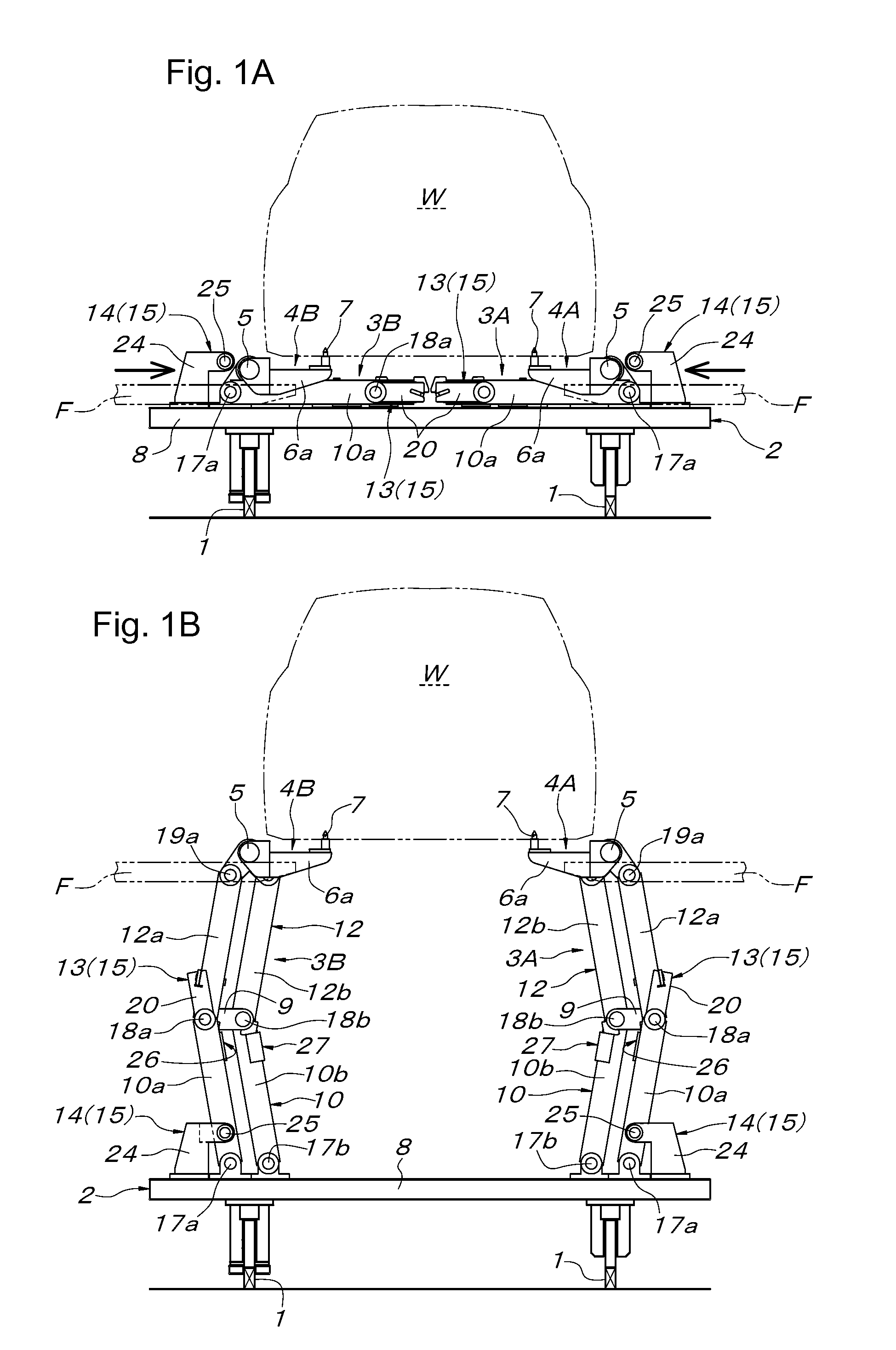
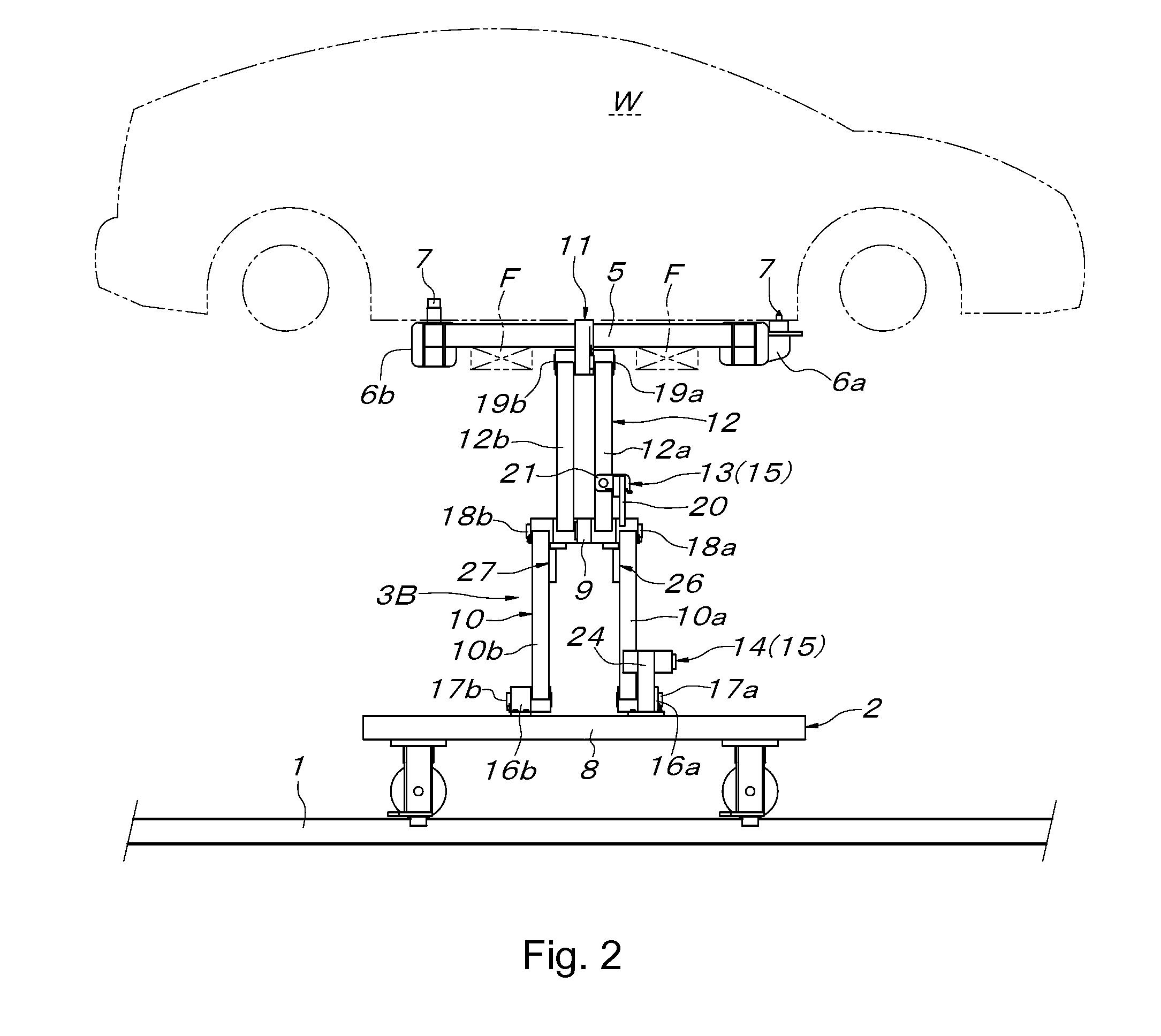
[0016]According to the configuration of the first aspect of the present invention, a workpiece such as an automobile body is supported by two workpiece supports having been supported by two center-folding double link mechanisms in the folded fallen-down posture, whereby the two workpiece supports (respective upper link members of the center-folding double link mechanisms) are integrally connected via the workpiece. Thus, the two workpiece supports (respective upper link members of the center-folding double link mechanisms) are vertically lifted up by a lifter or respective lower parallel links of the center-folding double link mechanisms are pushed upward by the drive means, whereby the workpiece supported on the workpiece supports can be vertically and parallelly raised along with expanding and rising of the two center-folding double link mechanisms. Once the workpiece is raised to a predetermined height, the lock means is operated to hold the two center-folding double link mechanisms in the expanding-rising posture having a predetermined angle. As a result, the workpiece can be supported stably at a predetermined height by the at least two center-folding double link mechanisms held in the expanding-rising posture.
[0017]More specifically, the workpiece is supported at the lowest position when the center-folding double link mechanisms are in the folded fallen-down posture, whereas the workpiece is supported at the highest position when the center-folding double link mechanisms are in the expanding-rising posture. Therefore, the center-folding double link mechanisms are switched between the folded fallen-down posture and the expanding-rising posture, whereby the height of their supporting workpiece can be switched between the lowest position and the highest position. Furthermore, if the lower parallel link and the upper parallel link are configured to expand substantially vertically collinearly when the center-folding double link mechanisms take the expanding-rising posture, the workpiece supports can be supported at relatively very high positions with respect to the lowest positions thereof when the center-folding double link mechanisms are in the folded fallen-down posture. Further, the center-folding double link mechanisms expanding substantially vertically linearly under the workpiece merely stand upright when the workpiece is supported at the highest position, so that a large
working space can be ensured under the workpiece.
[0018]Accordingly, the workpiece elevating support device of the present invention is used by being installed on a traveling carriage for conveying an automobile body in an automobile
assembly line, whereby the automobile body can be supported at heights suitable for respective working sections called a trim line and a final line where the automobile body needs to be supported at the lowest height of being close to a surface of the traveling carriage and a
chassis line where the automobile body needs to be supported at a level high enough for a worker to enter under the automobile body, by holding the center-folding double link mechanisms in the folded fallen-down posture in the trim line and the final line and by switching the center-folding double link mechanisms to the expanding-rising posture in the
chassis line. Furthermore, a large
working space can be ensured under the automobile body supported at the highest position, and accordingly, workability cannot be reduced. Further, the problems arising when the workpiece elevating support device is constituted by a lifter with the use of a column or a lifter with the use of a vertically expandable and contractible elevating body can all be solved.
[0019]According to the second aspect of the present invention and the third aspect of the present invention, the same effects as the first aspect of the present invention can be obtained, although on the condition that a lifter which supports and vertically elevates the workpiece support is used together.
[0020]Especially according to the configuration, the center-folding double link mechanisms in the folded fallen-down posture can be housed between the workpiece supported at the lowest position and the surface of the base (the traveling carriage), so that a large working space can be ensured at the periphery of the workpiece and workability can be improved compared with the case where a support means greatly projects outside the workpiece.
[0021]According to the configuration, the configuration of the lock means to hold the center-folding double link mechanisms in the expanding-rising posture is simplified, whereby the present invention can be carried out easily. Although the center-folding double link mechanisms can be held also in an expanding-rising posture of rising perfectly vertically linearly with respect to the base, the center-folding double link mechanisms in the expanding-rising posture can be held easily and stably according to the configuration, and the load applied to the lock means can be reduced. Further, according to the configuration, stability of the entire workpiece elevating support device having supported the workpiece at the highest position is increased, and the load applied to the lock means can be reduced. Further, the need to support the workpiece supports individually is eliminated also when elevated by a lifter, so that the elevation of the workpiece support by the lifter is facilitated. In addition, given that the workpiece supports are connected and integrated by their supporting workpiece or the configuration, the
combined use of the lifter which supports and elevates the workpiece support becomes unnecessary according to the configuration.


