Driving circuit for single-string LED lamp

a driving circuit and led lamp technology, applied in the direction of instruments, light sources, electroluminescent light sources, etc., can solve the problems of increasing the design cost of the driving circuit, and the inability to provide the standardization design for the connectors of the driving circuit used to connect to the led lamp, so as to achieve the effect of improving the common-use characteristi

Inactive Publication Date: 2012-07-19
TPV ELECTRONICS (FUJIAN) CO LTD
View PDF7 Cites 23 Cited by
  • Summary
  • Abstract
  • Description
  • Claims
  • Application Information

AI Technical Summary

Problems solved by technology

To balance current flowing through each string, the driving circuit has to use a specific-purpose integrated circuit (IC) having current balance function or a complex current balance circuit so as to increase the design cost of the driving circuit.
Moreover, LED lamps fabricated by different manufacturers or even by the same manufacturer have different input / output terminal designs and include different numbers of parallel strings so that it is impossible to provide the standardization design for connectors of the driving circuit used to connect to the LED lamp.
It results that the driving circuit for one LED lamp cannot be used for another LED lamp so as to waste human resources on the designs of the driving circuits for different LED lamps.

Method used


Image

  • Driving circuit for single-string LED lamp
  • Driving circuit for single-string LED lamp
  • Driving circuit for single-string LED lamp

Examples


Embodiment Construction

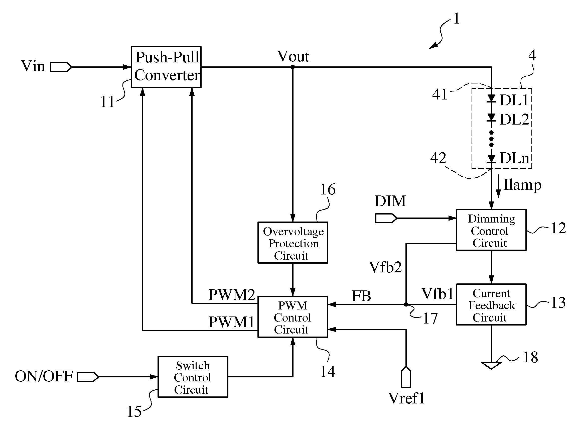
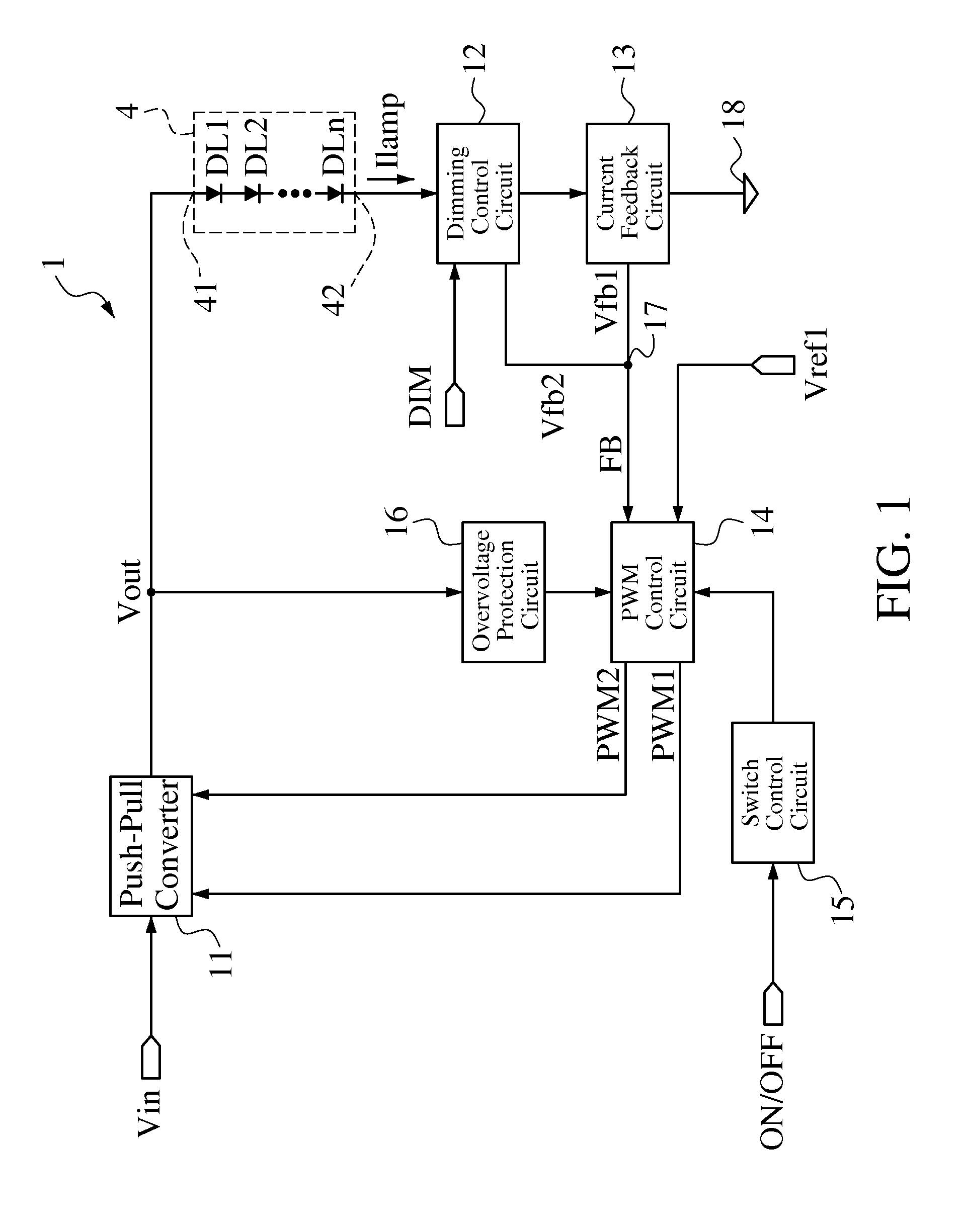
[0018]FIG. 1 is a schematic block diagram illustrating an embodiment of a driving circuit for a single-string LED lamp according to the present invention. Referring to FIG. 1, a single-string LED lamp 4 includes a plurality of LEDs DL1-DLn all coupled in series so as to have an input terminal 41 and an output terminal 42. An anode terminal of the LED DL1 is coupled to the input terminal 41, a cathode terminal of the LED DLi is coupled to an anode terminal of the LED DL(i+1) and a cathode terminal of the LED DLn is coupled to the output terminal 42, where i is any integer from 1 to (n−1). A driving circuit 1 for the single-string LED lamp 4 includes a push-pull converter 11, a dimming control circuit 12, a current feedback circuit 13, a PWM control circuit 14, a switch control circuit 15 and an overvoltage protection circuit 16. The dimming control circuit 12 and the current feedback circuit 13 are coupled in series between the output terminal 42 and a ground terminal 18. The PWM con...


PUM


Abstract

A driving circuit for a single-string light-emitting diode (LED) lamp includes a push-pull converter. The push-pull converter converts an input low DC voltage (such as 12-19V) to a high DC voltage (such as above 200V) to supply power to the single-string LED lamp. The driving circuit controls a lamp current flowing through the single-string LED lamp by means of constant current and adjusts brightness of the single-string LED lamp by means of pulse-width modulation (PWM) dimming. In addition, the single-string LED lamp provides the standardization design for connectors of the driving circuit used to connect to the single-string LED lamp so that the driving circuit has better common-use characteristic. Moreover, the driving circuit does not need a current balance circuit and only needs a cheaper and general-purpose integrated circuit to control the push-pull converter to reduce design cost of the driving circuit.

Description

BACKGROUND OF THE INVENTION[0001]1. Field of the Invention[0002]The present invention relates to a driving circuit for a light-emitting diode (LED) lamp. More particularly, the present invention relates to a driving circuit for a single-string LED lamp including a plurality LEDs all coupled in series.[0003]2. Description of the Related Art[0004]Liquid crystal displays (LCDs) such as LCD monitors, LCD television and all-in-one computers already used LED lamps as backlight sources. The LED lamp includes a plurality of LEDs coupled in series and / or parallel, such as eight parallel strings of ten LEDs coupled in series. A driving circuit for the LED lamp converts an input low DC voltage (such as 12-19V) to a high DC voltage (such as 30V-60V) to provide a supply voltage to drive the LED lamp, in which the supply voltage value is determined by the number of the LEDs of each string.[0005]Presently, the LED lamp usually uses multiple parallel strings such as four, six, eight parallel string...

Claims


Application Information

Patent Timeline
Patent Type & Authority Applications(United States)
IPC IPC(8): H05B37/02
CPCH05B33/0815H05B45/327H05B45/39
Inventor YU, ZUO-SHANGLEE, TSUNG-YEN
Owner TPV ELECTRONICS (FUJIAN) CO LTD
Why Eureka
Try Eureka