Liquid crystal display apparatus
- Summary
- Abstract
- Description
- Claims
- Application Information
AI Technical Summary
Benefits of technology
Problems solved by technology
Method used
Image
Examples
first embodiment
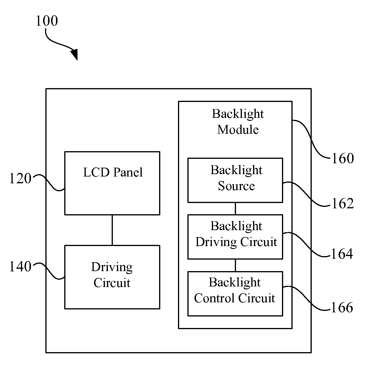
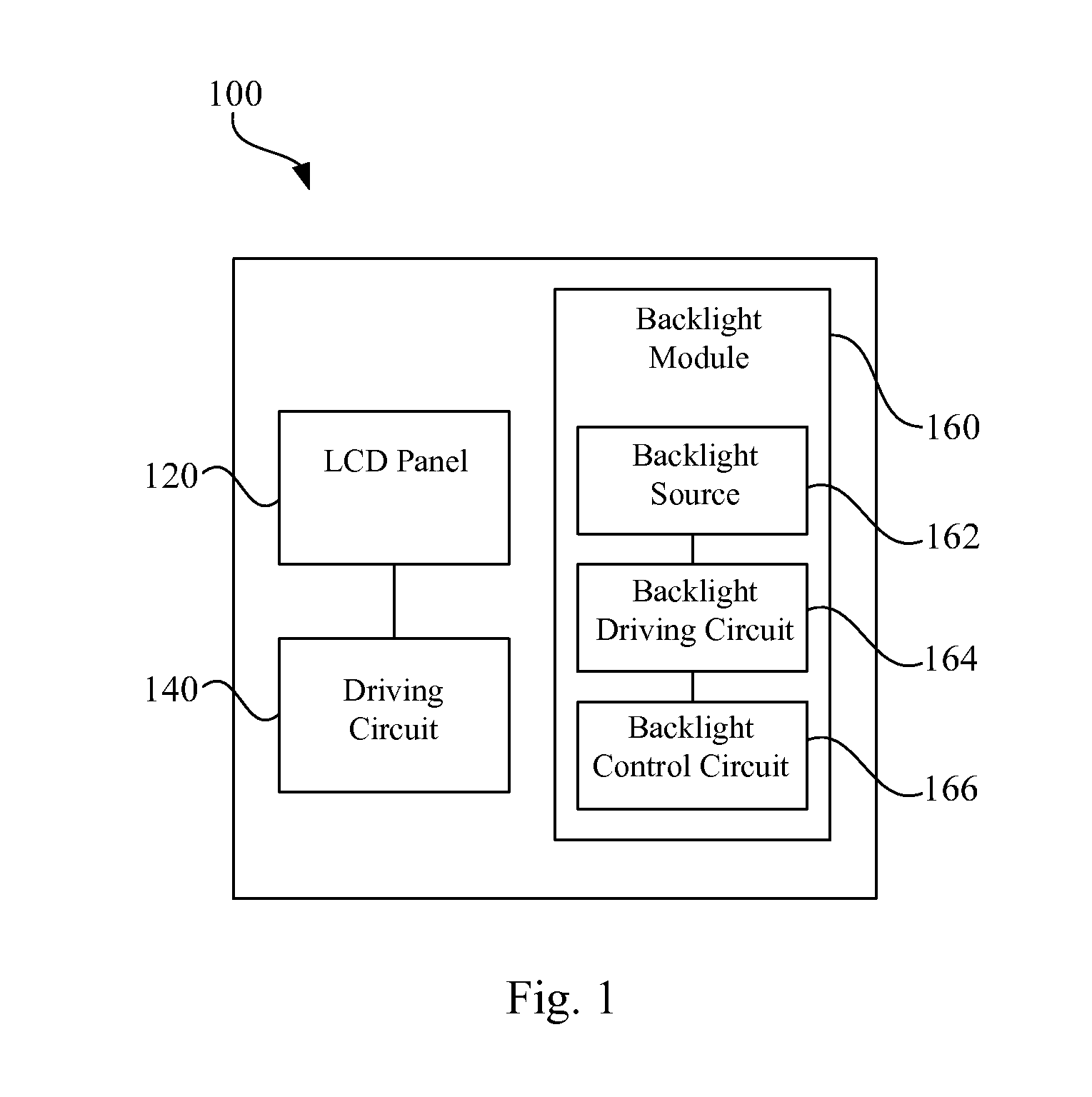
[0058]Referring to FIG. 1, FIG. 1 illustrates a function block diagram of a liquid crystal display (LCD) apparatus 100 with brightness / luminance holding ratio compensation according to the invention.
[0059]As shown in FIG. 1, the LCD apparatus 100 includes an LCD panel 120, a driving circuit 140 and a backlight module 160. The backlight module 160 includes a backlight source 162, a backlight driving circuit 164 and a backlight control circuit 166.
[0060]In an embodiment, the LCD panel 120 may be a transmissive or transflective LCD panel. Referring to FIG. 1, FIG. 1 is a schematic cross-sectional structural view of the LCD panel 120 in the first embodiment.
[0061]The LCD panel 120 has a refresh rate and a transmittance. The driving circuit 140 drives the LCD panel 120 according to the driving voltage. The transmittance of the LCD panel 120 is related to the driving voltage.
[0062]Hereinafter, the LCD panel 120 is for example a normally white mode LCD panel. Referring to FIGS. 2 and 3 tog...
second embodiment
[0085]In the second embodiment, if the LCD panel 120 is the normally white mode LCD panel, the backlight control circuit 166 controls the backlight driving circuit 164 to gradually or gradiently decrease the backlight driving current in the display frame cycle, so as to make the brightness / luminance of the backlight source 162 decrease over time.
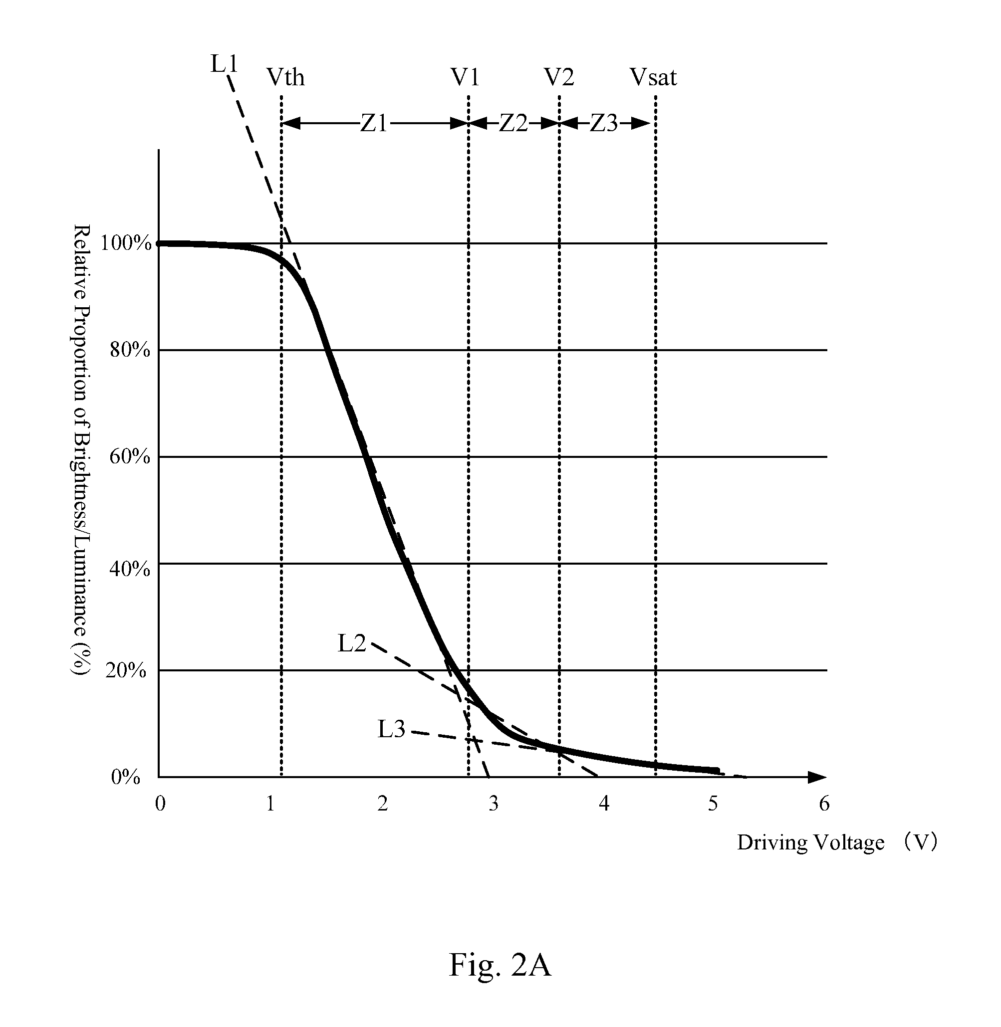
[0086]The variation curve of the transmittance or brightness versus the liquid crystal driving voltage of the LCD panel 120 is divided into a plurality of gray level intervals. Each of the gray level intervals corresponds to a compensation coefficient of the backlight control circuit. During each gray level interval, the backlight control circuit 166 gradually or gradiently decreases the backlight driving current according to the compensation coefficient, so as to make the brightness / luminance of the backlight source 162 decrease over time.
[0087]As shown in FIG. 2A, the gray level curve in FIG. 2A may be divided into several operating interv...
third embodiment
[0104]Next, referring to FIG. 6, FIG. 6 illustrates a function block diagram of an LCD apparatus 300 adopting a low-voltage gray level conversion method according to the invention. As shown in FIG. 6, the LCD apparatus 300 includes an LCD panel 320, a driving circuit 340, a control unit 380 and a backlight module 360. The backlight module 360 includes a backlight source 362, a backlight driving circuit 364 and a backlight control circuit 366. The control unit 380 further includes a calculation determining unit 382.
[0105]The LCD panel 320 is the transmissive or transflective normally white mode LCD panel. Referring to FIG. 2A, FIG. 2A illustrates a curve diagram of the driving voltage versus the brightness / luminance of the normally white mode LCD panel.
[0106]As shown in FIG. 2A, when the driving voltage of the normally white mode LCD panel 320 is low, the molecule arrangement of the normally white mode liquid crystal layer has the high transmittance mode, thus having the high brightn...
PUM
 Abstract
Description
Claims
Application Information
 - R&D
- Intellectual Property
- Life Sciences
- Materials
- Tech Scout
- Unparalleled Data Quality
- Higher Quality Content
- 60% Fewer Hallucinations
Browse by: Latest US Patents, China's latest patents, Technical Efficacy Thesaurus, Application Domain, Technology Topic, Popular Technical Reports.
© 2025 PatSnap. All rights reserved.Legal|Privacy policy|Modern Slavery Act Transparency Statement|Sitemap|About US| Contact US: help@patsnap.com


