Liquid-ejecting head and liquid-ejecting apparatus

a liquid ejector and recording head technology, applied in the direction of printing, inking apparatus, etc., can solve the problems of inability to maintain uniform liquid ejection quality, inability to produce difference between components contained in continuously ejecting ink droplets, and the problem of increasing the size of the recording head, so as to achieve enhanced liquid ejection quality and reduce the size of the apparatus

Active Publication Date: 2012-07-19
SEIKO EPSON CORP
View PDF1 Cites 41 Cited by
  • Summary
  • Abstract
  • Description
  • Claims
  • Application Information

AI Technical Summary

Benefits of technology

[0010]An advantage of some aspects of the invention is that it provides a liquid-ejecting head and liquid-ejecting apparatus, which can serve to suppress the increase of liquid viscosity and the precipitation of components contained in the liquid with the result that the quality of liquid ejection can be enhanced and which can be each provided so as to have a small size with the result that the production costs can be reduced.
[0012]In such a liquid-ejecting head, formation of the narrow portion enables a difference in channel resistance to be generated between the forward direction in which a liquid flows in the circulation channel and a direction opposite thereto. A liquid can be therefore circulated only as a result of generating pressure change in the liquid in the channel by the pressure generator, and use of an additional unit such as a pump is accordingly excluded, thereby being able to reduce the size of the liquid-ejecting head and production costs.
[0013]It is preferable that a plurality of the narrow portions are provided. By virtue of such a configuration, a difference (ratio) in the channel resistance between the forward direction and the direction opposite thereto can be increased.
[0016]It is preferable that the channel includes a common liquid chamber that is in communication with a plurality of the pressure-generating chambers in common. In addition, it is preferable that the circulation channel has one end that is in communication with the common liquid chamber and has the other end that is in communication with each of the pressure-generating chambers. By virtue of such a configuration, a liquid in the vicinity of the nozzle opening can be circulated. Furthermore, drying of a liquid immediately before being ejected can be steadily suppressed, and the precipitation of components contained in the liquid can be also steadily suppressed.
[0018]In such a liquid-ejecting apparatus, the quality of liquid ejection can be enhanced, and the size of the apparatus can be reduced.

Problems solved by technology

Variation is therefore caused in ink droplet ejection characteristics with the passage of time, and the quality of liquid ejection cannot be accordingly uniformly maintained.
In addition, components contained in ink precipitate with the result that difference is generated between components contained in a continuously ejected ink droplet and components contained in an intermittently ejected ink droplet.
The size of the recording head is therefore problematically increased, and production costs are also disadvantageously increased.
Such disadvantages arise not only in the ink jet recording head from which ink is ejected but in a liquid-ejecting head from which liquids other than the ink are ejected.

Method used


Image

  • Liquid-ejecting head and liquid-ejecting apparatus
  • Liquid-ejecting head and liquid-ejecting apparatus
  • Liquid-ejecting head and liquid-ejecting apparatus

Examples


first embodiment

[0034

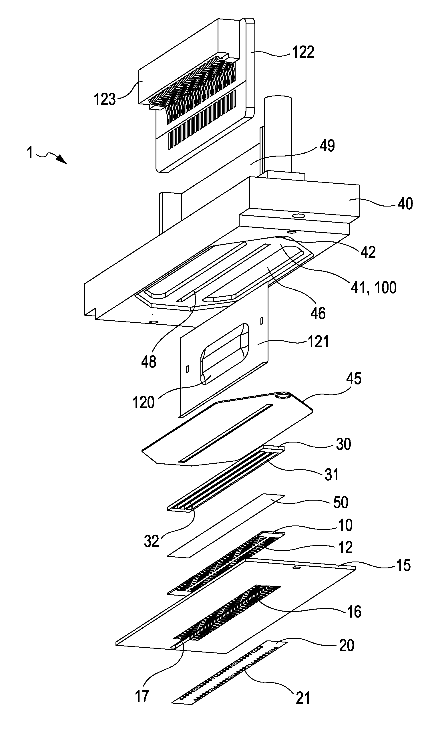
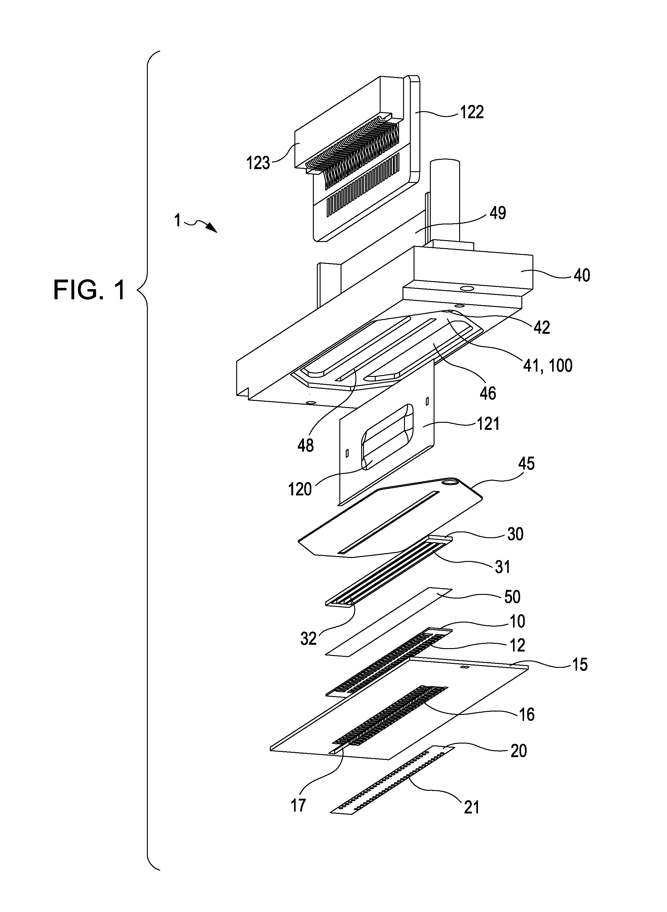
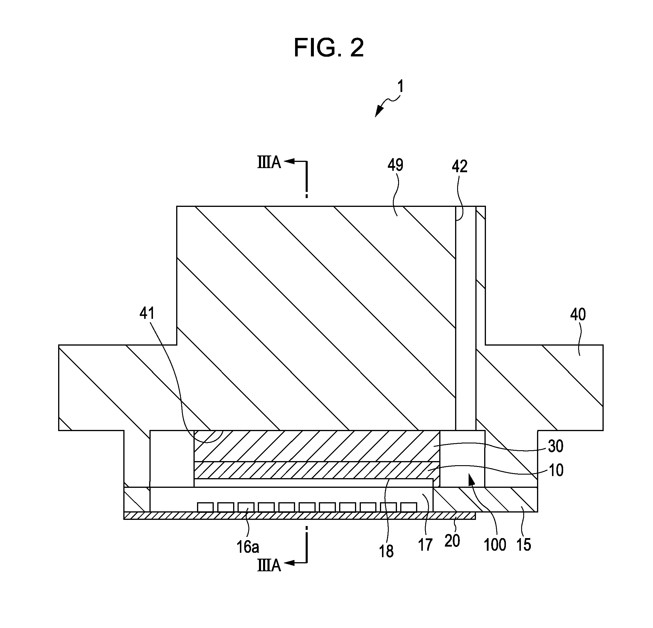
[0035]FIG. 1 is an exploded perspective view illustrating an ink jet recording head as an example of a liquid-ejecting head of the first embodiment of the invention. FIG. 2 is a cross-sectional view illustrating the ink jet recording head in the lateral direction of a pressure-generating chamber. FIG. 3A is a cross-sectional view illustrating the ink jet recording head taken along the line IIIA-IIIA in FIG. 2, and FIG. 3B is a cross-sectional view partially illustrating the ink jet recording head in FIG. 3A in an enlarged manner. FIG. 4 is a cross-sectional view illustrating a channel configuration. In this embodiment, a silicon single-crystal substrate having a (110) orientation is used to form a channel-forming substrate 10, and an elastic film 50 that is made by using silicon dioxide is provided on one surface of the channel-forming substrate 10 as illustrated in the drawings. The channel-forming substrate 10 has two lines individually including a plurality of pressure-gener...

second embodiment

[0075

[0076]FIGS. 9A and 9B are each a cross-sectional view illustrating an ink jet recording head as an example of a liquid-ejecting head of a second embodiment of the invention. FIG. 10 is a plan view illustrating a channel-forming substrate.

[0077]With reference to FIG. 9A, an ink jet recording head 1A of this embodiment includes a channel-forming substrate 410 in which a plurality of pressure-generating chambers 412 are formed in parallel; a nozzle plate 420 in which nozzle openings 421 are formed so as to be in communication with the corresponding pressure-generating chambers 412; a vibrating plate 450 which is formed on a surface of the channel-forming substrate 410, such a surface being opposite to the nozzle plate 420; and a piezoelectric actuators 500 which are formed so as to overlie the vibrating plate 450.

[0078]With reference to FIGS. 9A to 10, the pressure-generating chambers 412 are formed such that the channel-forming substrate 410 is segmented by partitions and are ali...


PUM


Abstract

A liquid-ejecting head includes a channel which is in communication with a nozzle opening and which includes a pressure-generating chamber, a circulation channel that serves to circulate a liquid in the channel, and a pressure generator that serves to generate pressure change. The circulation channel has a narrow portion including a first wall and a second wall, the first wall tilting with respect to a forward direction of a liquid flows and serving to gradually decrease the cross-sectional area, the second wall tilting with respect to the flow direction and serving to gradually increase the cross-sectional area. The tilt angle of the first wall with respect to the inner surface of the circulation channel is larger than the tilt angle of the second wall with respect to the inner surface of the circulation channel at the downstream side.

Description

[0001]THIS APPLICATION CLAIMS A PRIORITY TO JAPANESE PATENT APPLICATION NO. 2011-004596 FILED ON JAN. 13, 2011 WHICH IS HEREBY EXPRESSLY INCORPORATED BY REFERENCE HEREIN IN ITS ENTIRETY.BACKGROUND[0002]1. Technical Field[0003]The present invention relates to a liquid-ejecting head and liquid-ejecting apparatus in which liquid is ejected from a nozzle opening, especially relates to an ink jet recording head and ink jet recording apparatus in which ink is ejected as the liquid.[0004]2. Related Art[0005]An ink jet recording head is one of typical examples of a liquid-ejecting head from which a droplet is ejected. Examples of the ink jet recording head include a recording head which includes a channel-forming substrate having a pressure-generating chamber and a piezoelectric actuator provided on one surface of the channel-forming substrate. In such a recording head, the piezoelectric actuator is deformed to apply pressure to the inside of the pressure-generating chamber, thereby ejectin...

Claims


Application Information

Patent Timeline
Patent Type & Authority Applications(United States)
IPC IPC(8): B41J2/04
CPCB41J2/14233B41J2/14274B41J2002/14362B41J2/045B41J2002/14491B41J2202/12B41J2002/14467
Inventor AKAHANE, FUJIOTAKAHASHI, TOMOAKI
Owner SEIKO EPSON CORP
Why Eureka
Try Eureka