Endoscope system and low visibility determining method

a technology of endoscope and determining method, which is applied in the field of endoscope system and low visibility determining method, can solve problems such as smoke or mist generation

Active Publication Date: 2012-07-19
OLYMPUS CORP
View PDF1 Cites 37 Cited by
  • Summary
  • Abstract
  • Description
  • Claims
  • Application Information

AI Technical Summary

Benefits of technology

[0010]An endoscope system according to an aspect of the present invention includes an image pickup section, provided in an endoscope, that performs image pickup, a determining section that determines whether or not a specific observation object exists inside an image pickup region of the image pickup section, a recognizing section that determines whether or not the specific observation object can be recognized as an image from the picked-up image in the image pickup region picked up by the image pickup section, a low visibility determination output section that determines, when the determining section determines that the specific observation object exists inside the image pickup region and the recognizing section cannot recognize the specific observation object as an image, that the image pickup section is in a low visibility condition and outputs a low visibility determination result, and an obstacle estimation section that estimates an obstacle or a type of obstacle which causes the low visibility according to the low visibility determination result.
[0011]A low visibility determining method according to an aspect of the present invention includes a display step of displaying an image of a site to be observed in a body cavity picked up by an image pickup section as an endoscope image, a treatment instrument position acquiring step of a position determining section acquiring a position of a distal end portion of a treatment instrument for conducting a treatment of the site to be observed, a position determining step of the position determining section determining whether or not the distal end portion of the treatment instrument is located inside an image pickup region as a region of the picked-up image, a recognizing step of an image recognizing section conducting image recognition as to whether or not the distal end portion of the treatment instrument can be recognized as an image of an interior of the image pickup region through image processing on the picked-up image, a low visibility determination outputting step of a low visibility determining section determining low visibility when the distal end portion of the treatment instrument is determined in the position determining step to be inside the image pickup region and the recognition result in the recognizing step shows that the distal end side of the treatment instrument cannot be recognized as an image inside the image pickup region and outputting a low visibility determination result, and an obstacle estimating step of an obstacle estimation section estimating, when the low visibility determination result is outputted in the low visibility determination outputting step, an obstacle or a type of obstacle that causes the low visibility.

Problems solved by technology

Smoke or mist may be generated when conducting a treatment on the tissue.

Method used


Image

  • Endoscope system and low visibility determining method
  • Endoscope system and low visibility determining method
  • Endoscope system and low visibility determining method

Examples


first embodiment

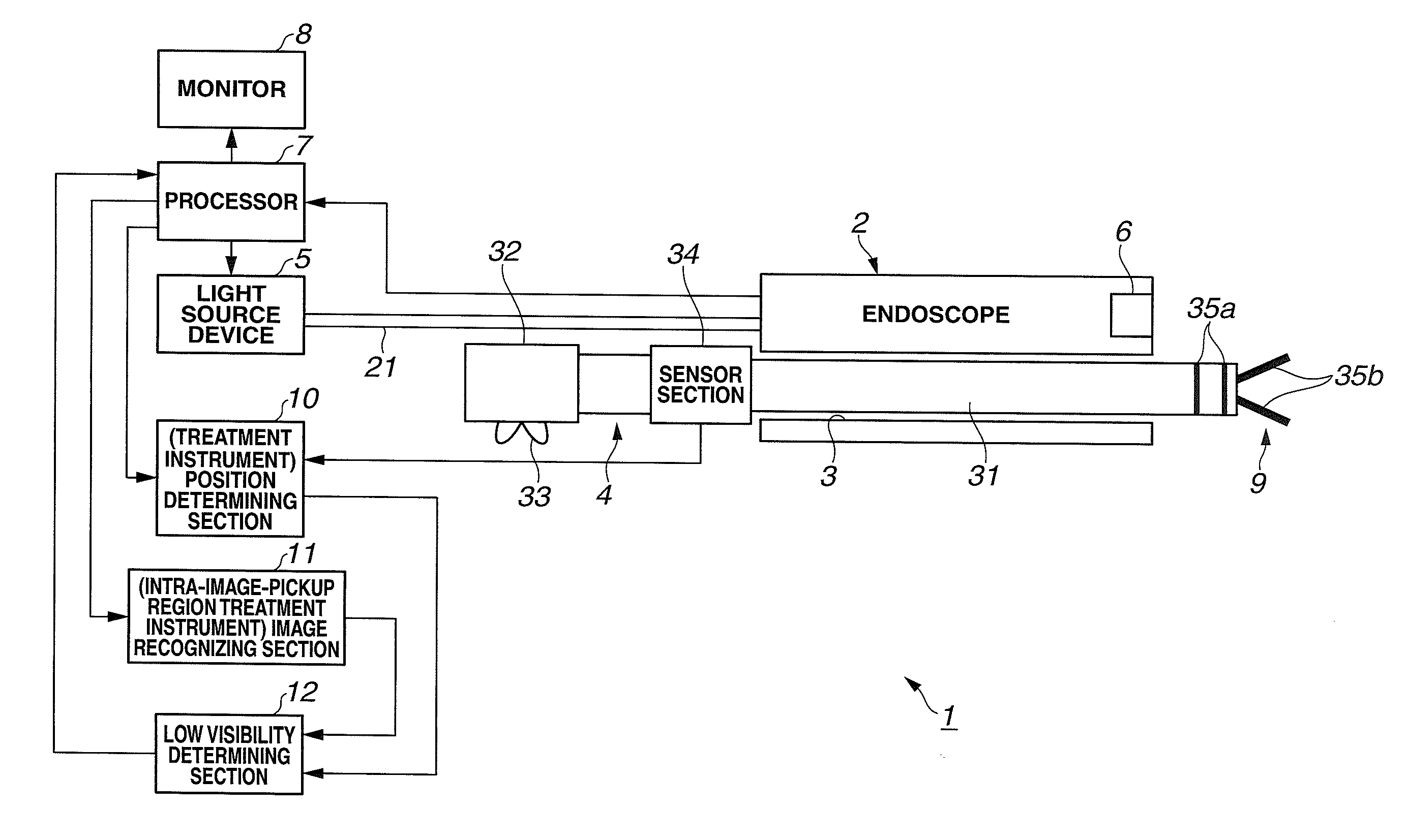
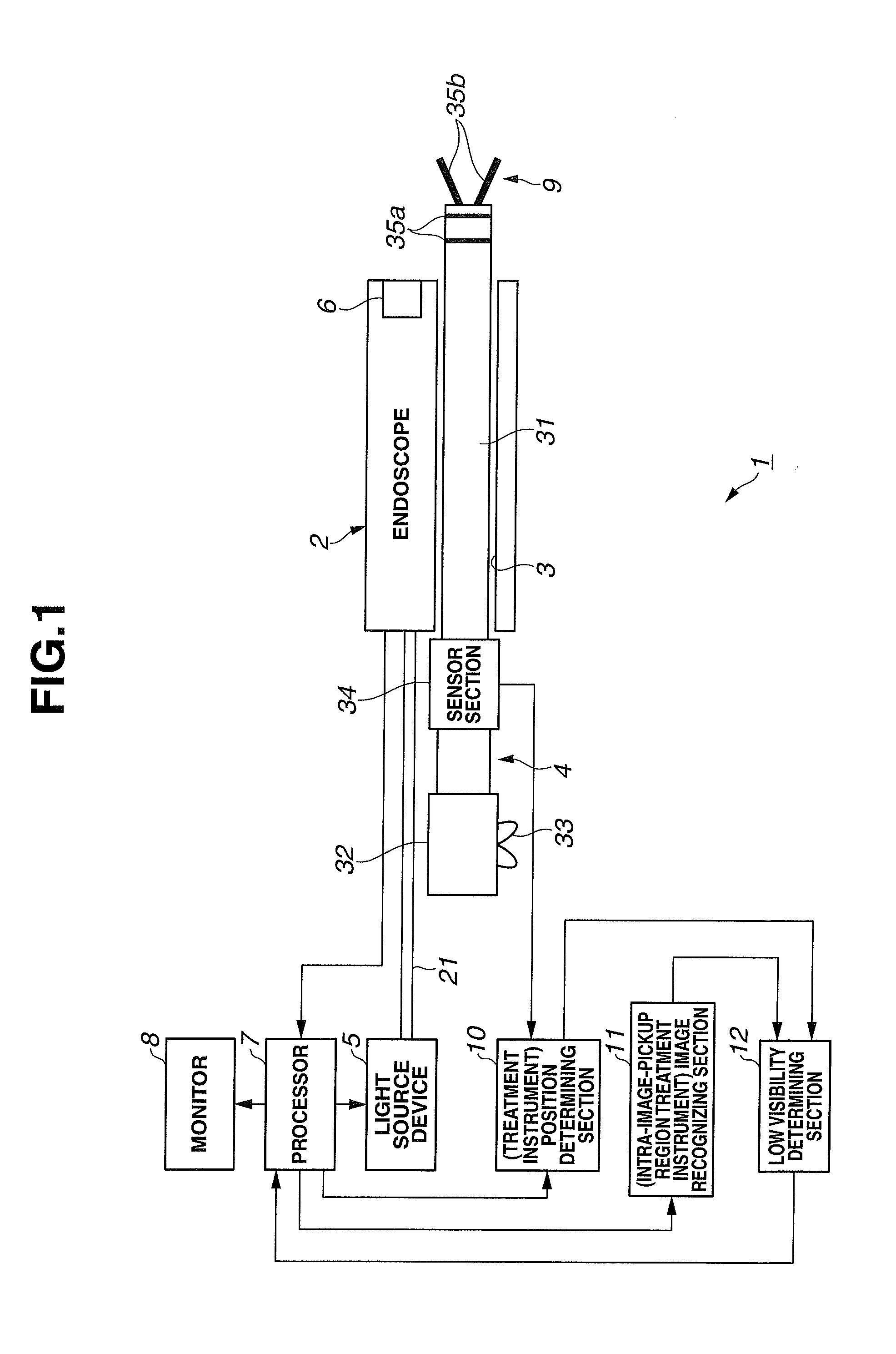
[0032]As shown in FIG. 1, an endoscope system 1 according to a first embodiment of the present invention includes an endoscope 2 inserted into a body, a treatment instrument 4 inserted into a treatment instrument channel (simply abbreviated as “channel”) 3 of the endoscope 2 and a light source device 5 that supplies illuminating light to the endoscope 2.

[0033]Furthermore, this endoscope system 1 includes a processor 7 as signal processing means for performing signal processing with respect to an image pickup section 6 as image pickup means provided in the endoscope 2 and a monitor 8 as display means for displaying an endoscope image corresponding to an image signal generated by the processor 7.

[0034]The light source device 5 and the processor 7 may be connected together via a signal line and a light quantity of illuminating light from the light source device 5 may be adjusted by a brightness signal of the image signal from the processor 7.

[0035]Furthermore, this endoscope system 1 i...

second embodiment

[0096]Next, a second embodiment of the present invention will be described with reference to FIG. 5 to FIG. 9. FIG. 5 illustrates an overall configuration of an endoscope system 1B according to the second embodiment of the present invention.

[0097]The endoscope system 1B shown in FIG. 5 corresponds to the endoscope system 1 in FIG. 1 using a high-frequency treatment instrument 4B that performs a treatment using high-frequency electric energy instead of the treatment instrument 4 and this high-frequency treatment instrument 4B is connected to a high-frequency power supply apparatus 41 as an electric energy supply apparatus.

[0098]Furthermore, this high-frequency power supply apparatus 41 is connected to a foot switch (abbreviated as “FS” in FIG. 5) 42 that performs an instruction operation to output or stop outputting a high-frequency current (ON / OFF). The high-frequency treatment instrument 4B, the high-frequency power supply apparatus 41 and the foot switch 42 constitute a high-frequ...

third embodiment

[0158]Next, a third embodiment of the present invention will be described with reference to FIG. 10 to FIG. 12. FIG. 10 is a diagram illustrating an overall configuration of an endoscope system 1C according to the third embodiment of the present invention.

[0159]The endoscope system 1C corresponds to the endoscope system 1B according to the second embodiment shown in FIG. 5 using an active high-frequency treatment instrument (simply abbreviated as “high-frequency treatment instrument”) 4C provided with a drive section 50 that actively drives a moving section instead of the manual high-frequency treatment instrument 4B. This high-frequency treatment instrument 4C, a high-frequency power supply apparatus 41 and a foot switch 42 form a high-frequency electrocoagulation apparatus 43C.

[0160]Furthermore, the endoscope system 1C of the present embodiment is provided with a control section 51 that controls operation of the high-frequency treatment instrument 4C and also controls an energy su...


PUM


Abstract

An endoscope system includes an image pickup section, provided in an endoscope, which performs image pickup, a determining section that determines whether a specific observation object exists inside an image pickup region of the image pickup section, a recognizing section that determines whether the specific observation object can be recognized as an image from the picked-up image in the image pickup region picked up by the image pickup section, a low visibility determination output section that determines, when the determining section determines that the specific observation object exists inside the image pickup region and the recognizing section cannot recognize the specific observation object as an image, that the image pickup section is in a low visibility condition and outputs a low visibility determination result, and an obstacle estimation section that estimates an obstacle or a type of obstacle which causes the low visibility according to the low visibility determination result.

Description

CROSS REFERENCE TO RELATED APPLICATION[0001]This application is a continuation application of PCT / JP2011 / 068626 filed on Aug. 17, 2011 and claims benefit of Japanese Application No. 2010-205896 filed in Japan on Sep. 14, 2010, the entire contents of which are incorporated herein by this reference.BACKGROUND OF THE INVENTION[0002]1. Field of the Invention[0003]The present invention relates to an endoscope system and a low visibility determining method that performs image pickup using image pickup means of an endoscope and determines low visibility.[0004]2. Description of the Related Art[0005]In recent years, endoscopes provided with image pickup means are widely used for an observation and diagnosis or the like of diseased tissues. Furthermore, endoscopes are also widely used when conducting a surgical operation using a high-frequency treatment instrument making up a high-frequency electrocoagulation apparatus under observation with an endoscope.[0006]Under observation with an endosc...

Claims


Application Information

Patent Timeline
Patent Type & Authority Applications(United States)
IPC IPC(8): H04N7/18G06K9/00
CPCA61B1/00006A61B1/05A61B1/00009A61B1/000094
Inventor MORIYAMA, HIROKIUMEMOTO, YOSHITAKA
Owner OLYMPUS CORP
Why Eureka
Try Eureka