
Medical image display apparatus, method, and program

a medical image and display device technology, applied in healthcare informatics, instruments, ultrasonic/sonic/infrasonic diagnostics, etc., can solve the problem of difficult to accurately recognize which position in the medical image, and achieve the effect of easy reference, accurate image reading, and accurate positioning of the lesion area

Active Publication Date: 2012-07-19
FUJIFILM CORP
View PDF8 Cites 38 Cited by
  • Summary
  • Abstract
  • Description
  • Claims
  • Application Information

AI Technical Summary

Benefits of technology

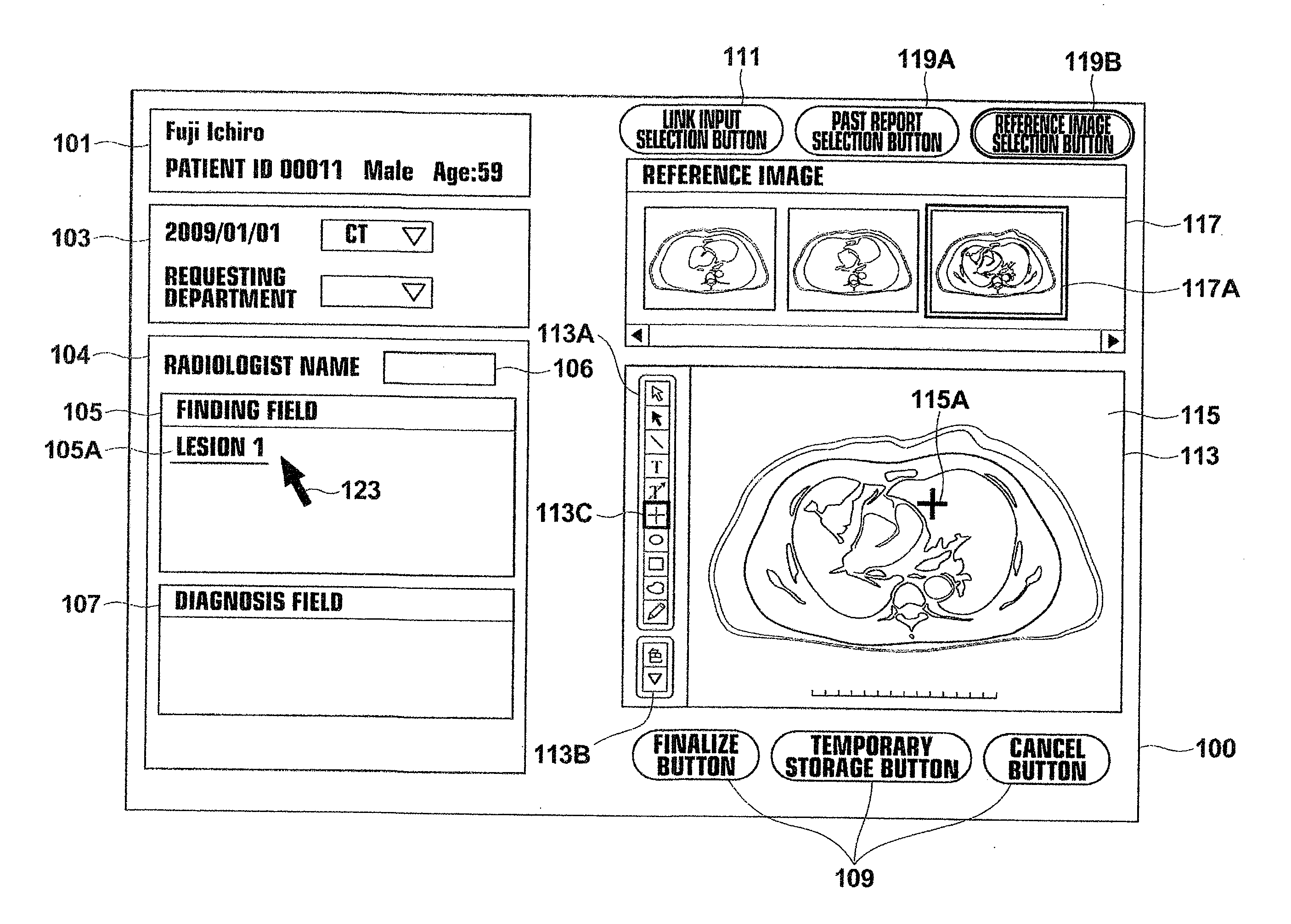
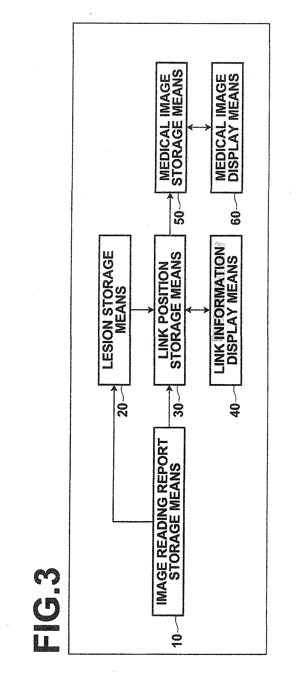
[0044]According to the image reading report display apparatus, method, and program of the present invention, an image reading report in which a position of a lesion area in a first medical image and a lesion character representing the lesion are associated is stored, the lesion character and the position of the lesion area are stored in association with each other, and a link character constituted by the lesion character and a position indicator indicating the link position corresponding to the position of the lesion area represented by the link character are displayed in a second medical image reconstructed from a plurality of medical images, including the first medical image, in association with each other. This allows the position of the lesion area and a character string representing the lesion to be referenced in the second medical image, whereby the position of the lesion area may be accurately recognized.
[0050]In the case where the image reading report includes a plurality of image reading reports with respect to past medical images or with respect to a plurality of different lesion positions, information of a plurality of image reading reports may be referenced and image reading may be performed accurately.

Problems solved by technology

Further, it has been difficult to accurately recognized as to which position in the medical image the lesion described in the image reading report corresponds to, as one medical image is linked to one character string in the image reading report.

Method used


Image

  • Medical image display apparatus, method, and program
  • Medical image display apparatus, method, and program
  • Medical image display apparatus, method, and program

Examples


first embodiment

[0076]A portion of the system relevant to the medical image processing function according to the present invention will now be described.

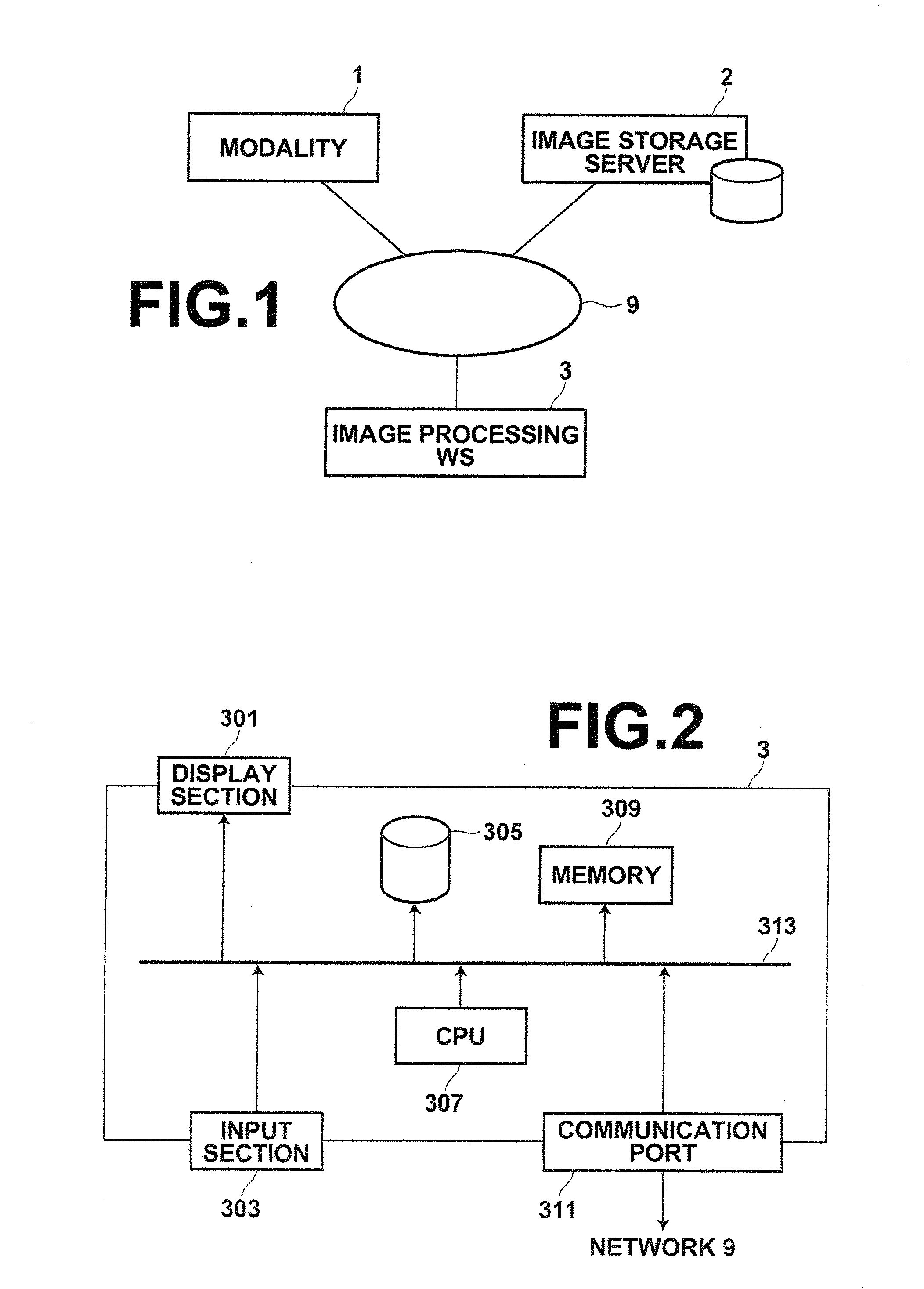
[0077]FIG. 2 is a schematic block diagram of workstation 3, illustrating the configuration thereof. As illustrated in FIG. 2, the medical image display apparatus according to an embodiment of the present embodiment is made up of image processing workstation 3 that includes display section 301, such as a liquid crystal monitor, for performing various types of display operations, input section 303 that includes a keyboard and mouse for performing various types of input operations, hard disk 305 for storing various types of programs for controlling the medical image display apparatus according to the present embodiment, including the medical image processing program of the present invention, and various types of data such as image data and the like, CPU 307 for controlling the medical image display apparatus according to the present embodiment through...

second embodiment

[0132]Further, in the second embodiment, link information display means 40 displays the link character 137A in the medical image by linking the character to the corresponding lesion character 141 described in the image reading report by a hyperlink.

[0133]By way of example, a medical image display according to the second embodiment will be described with reference to FIG. 11. FIG. 11 shows, by way of example, medical image display screen 110 according to the second embodiment. In medical image display screen 110 shown in FIG. 11, a phrase before and after the lesion character 141 described in the image reading report is displayed in addition to the link character 137A, as shown in a comment 137D. Likewise, in addition to the link character 135A, a phrase before and after the lesion character corresponding to the link character 135A described in the image reading report is displayed, as shown in a comment 135D. Components given the same reference numerals as those in FIG. 8 are identi...

third embodiment

[0141]Next, a third embodiment will be described. Image reading report storage means 10 stores a plurality of image reading reports, including past image reading reports with respect to past medical images of the same patient. Lesion storage means 20 converts a lesion position in a past medical image to the corresponding lesion position in a current image representing the same region and same position and stores as lesion information. More specifically, with respect to a slice image 143 representing a lesion position in a past medical image, a medical image constituted by a group of tomographic images, including the past slice image 143, is aligned with a medical image constituted by a group of current tomographic images using the technique described in Japanese Unexamined Patent Publication No. 2009-72432 of the present inventor and coordinates representing the lesion position in the slice image 143 are obtained as the coordinates of attention point in the corresponding current med...


PUM


Abstract

Storing a second image reconstructed from a plurality of images, including a first image, and an image reading report that includes a lesion character representing a lesion area in the first image. Associating the lesion character with a position of the lesion area and storing the position in the second image corresponding to the position of the lesion area as a link position. Displaying a link character constituted by the lesion character, a position indicator indicating the link position corresponding to the position of the lesion area represented by the link character, and an association indicator indicating the link character and position indicator in association with each other in the second medical image.

Description

BACKGROUND OF THE INVENTION[0001]1. Field of the Invention[0002]The present invention relates to a medical image display apparatus, method, and program, and more particularly to a medical image display apparatus, method, and program for displaying, when a lesion character in an image reading report is specified, an image of the lesion area.[0003]2. Description of the Related Art[0004]Recently, medical image display technologies for reconstructing and displaying medical images have been evolving and serving as assistance in image diagnosis performed in the medical field as described, for example, in Japanese Unexamined Patent Publication Nos. 5 (1993)-189541 and 7 (1995)-021405.[0005]In image diagnoses using medical images, in general, diagnosticians make diagnoses with reference to image reading reports generated by radiologists. Some image reading reports allow a reference image to be linked to a character string in the reports as described, for example, in Japanese Unexamined Pate...

Claims


Application Information

Patent Timeline
Patent Type & Authority Applications(United States)
IPC IPC(8): G06K9/00G16H15/00G16H30/20G16H30/40
CPCG06F19/321G06F19/3487G06T19/00A61B6/463A61B8/5261A61B6/5247A61B8/463A61B8/5223A61B6/5217G16H15/00G16H30/20G16H30/40
Inventor MORIYA, YOSHIYUKI
Owner FUJIFILM CORP
Learn More