Developer container and image forming apparatus

a technology developer container, which is applied in the field of developer container, can solve the problems of large toner consumption of image forming apparatus operating at high speed, and achieve the effects of reducing the amount of toner consumed, facilitating stirring, and stably dischargeing a certain amount of developer

Active Publication Date: 2012-07-19
SHARP KK
View PDF1 Cites 11 Cited by
  • Summary
  • Abstract
  • Description
  • Claims
  • Application Information

AI Technical Summary

Benefits of technology

[0015]According to the configuration, the first discharge opening is formed in the inclined surface of the edge part of the developer vessel. The inclined surface inclines, upstream of the direction in which the developer is carried along the shaft line of the developer vessel, so as to be at angles with the surface perpendicular to the shaft line. Therefore, in a case where the developer vessel contains plenty of developer, the inclined surface makes it easy to stir and flow developer located in the vicinity of the first discharge opening upon the rotation of the developer vessel around the shaft line. The inclined surface also makes it possible to discharge plenty of developer from the developer vessel through the first discharge opening formed in the inclined surface. According to the configuration, it is possible to stably discharge a certain large amount of developer, as compared with a case where the first discharge opening is formed in the surface of the edge part of the developer vessel which surface is perpendicular to the shaft line.
[0016]A decrease in amount of developer contained in the developer vessel (i) makes it easy to stir the developer contained in the developer vessel in response to the rotation of the developer vessel and (ii) causes a decrease in time period during which the first discharge opening is closed by the developer contained in the developer vessel. This allows the outside air to easily flow into the developer vessel. Hence, plenty of toner can be continuously discharged.
[0017]It is thus possible to stably discharge a certain large amount of developer from the developer container, regardless of quantity of the developer contained in the developer vessel. Further, according to the configuration, the developer container includes the developer supply section which is configured to surround the periphery of the first discharge opening.
[0018]This makes it possible to prevent an image forming apparatus from upsizing and cost rise.

Problems solved by technology

An image forming apparatus that operates at high speed consumes plenty of toner.

Method used


Image

  • Developer container and image forming apparatus
  • Developer container and image forming apparatus
  • Developer container and image forming apparatus

Examples


embodiment

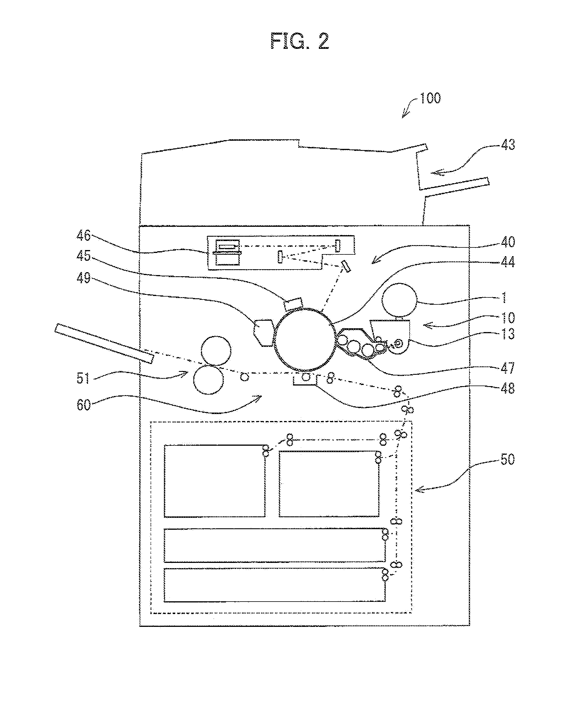
[0029]The following description will discuss in detail an embodiment of the present invention with reference to drawings. FIG. 2 is an example of an embodiment of the present invention, and is an explanatory drawing illustrating an entire configuration of an image forming apparatus of the present invention. The image forming apparatus employs a later-described toner cartridge (developer container) of the present invention. Note that a copying machine shown in FIG. 2 is exemplified as the image forming apparatus of the present invention. However, the image forming apparatus of the present invention is not limited to the copying machine, provided that it is an apparatus, such as a printer, a facsimile, or a copying machine, which forms an image, i.e., provided that it is an apparatus which forms an image and from which the toner cartridge (later described) of the present invention is detachable.

[0030]As shown in FIG. 2, the image forming apparatus 100 includes a document reading secti...

example

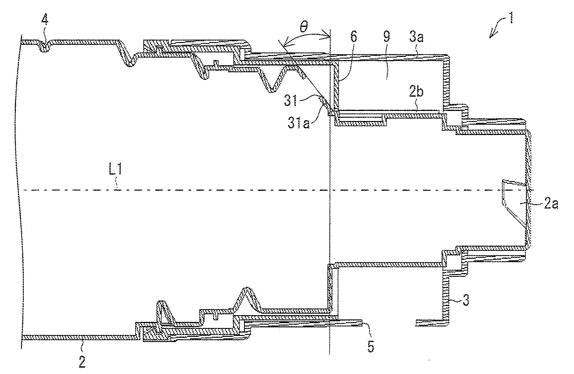
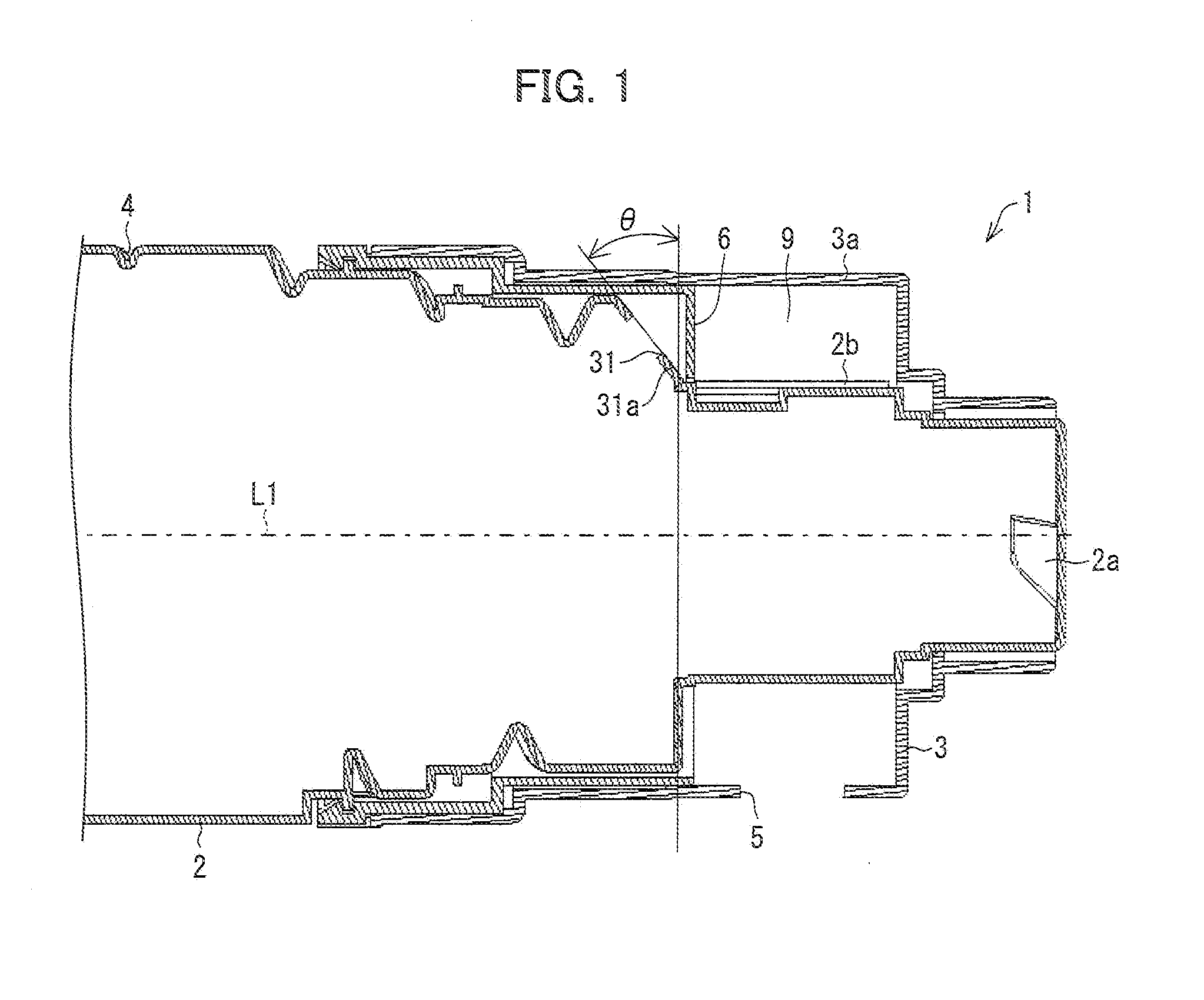
[0053]An experiment was carried out. In the experiment, a relationship between quantity of toner left in a toner bottle and quantity of toner discharged from a toner cartridge was analyzed by use of (i) the toner cartridge 1 of the present embodiment in which the angle θ of the inclined surface 31a of the toner bottle 2 was 40° (Example) and (ii) the conventional toner cartridge 101 (Comparative Example) shown in FIGS. 8 and 9. In this experiment, the toner cartridge of Example was configured identically to the toner cartridge of Comparative Example, except that the angle θ of a surface in which a discharge opening of a toner bottle was formed was 40° in Example, whereas an angle θ of a surface in which a discharge opening of a toner bottle was formed was 0° in Comparative Example.

[0054]Note that the discharge openings of the toner bottles of Example and Comparative Example had an identical surface area. Further, toner contained in the toner bottle of Example was identical in quanti...


PUM


Abstract

A developer container 1 includes (i) a developer vessel 2, having a cylindrical shape, that carries and discharges toner contained therein through its first discharge opening 31 while the developer vessel 2 is being driven to rotate, and (ii) a developer supply section 3 which (a) supports the developer vessel 2 such that the developer vessel 2 can rotate, (b) temporarily stores the toner discharged from the first discharge opening 31, and (c) discharges the toner outside of the developer supply section 3 from a second discharge opening 5. The first discharge opening 31 is formed in an inclined surface 31a of an edge part of the developer vessel 2. The inclined surface 31a inclines, upstream of a direction in which the toner is carried along a shaft line L1, so as to be at angles with a surface perpendicular to the shaft line L1.

Description

[0001]This Nonprovisional application claims priority under 35 U.S.C. §119(a) on Patent Application No. 2011-005119 filed in Japan on Jan. 13, 2011, the entire contents of which are hereby incorporated by reference.TECHNICAL FIELD [0002]The present invention relates to a developer container that contains developer, in particular, relates to (i) a developer container that discharges contained developer by being driven to rotate and (ii) an image forming apparatus including the developer container.BACKGROUND ART [0003]In an electrophotographic image forming apparatus, an electrostatic latent image formed on a surface of a photoreceptor is made visible by use of toner (developer) by a developing device. The toner used for making the electrostatic latent image visible is contained in a toner container, and sequentially supplied to the developing device from the toner container.[0004]An image forming apparatus that operates at high speed consumes plenty of toner. Therefore, a toner conta...

Claims


Application Information

Patent Timeline
Patent Type & Authority Applications(United States)
IPC IPC(8): G03G15/08
CPCG03G15/087G03G15/0872
Inventor OHGOSHI, TOSHIHIDEMIHARA, KOICHI
Owner SHARP KK
Why Eureka
Try Eureka