Power supply device, power receiving device, and power supply method

a technology of power supply device and power receiving device, which is applied in power management, instruments, liquid/fluent solid measurement, etc., can solve the problem of increasing the number of ac adaptors with increasing the number of devices

Inactive Publication Date: 2012-07-19
SONY CORP
View PDF5 Cites 25 Cited by
  • Summary
  • Abstract
  • Description
  • Claims
  • Application Information

AI Technical Summary

Benefits of technology

[0006]In the power bus systems disclosed in the Patent Literature references 1 and 2, for example, all communications between a server and a client are performed through a bus line. Meanwhile, as a mechanism for feeding electric power, there is wireless power transfer using a magnetic line and the like, and when the power feeding mechanism such as wireless power transfer is incorporated in the power bus system, it is inappropriate to support wire-based communication. The present inventors recognized that this conventional approach does not allow for client devices to distinguish between different power servers that may be able to provide different power formats for conveying power to the client devices wirelessly or directly.

Problems solved by technology

Thus, even if AC adaptors have similar shapes, they can be incompatible with each other, and there is an issue that the number of AC adaptors increases with increasing numbers of devices.

Method used


Image

  • Power supply device, power receiving device, and power supply method
  • Power supply device, power receiving device, and power supply method
  • Power supply device, power receiving device, and power supply method

Examples


first embodiment

1. First Embodiment

1-1. Constitution of Power Supply System

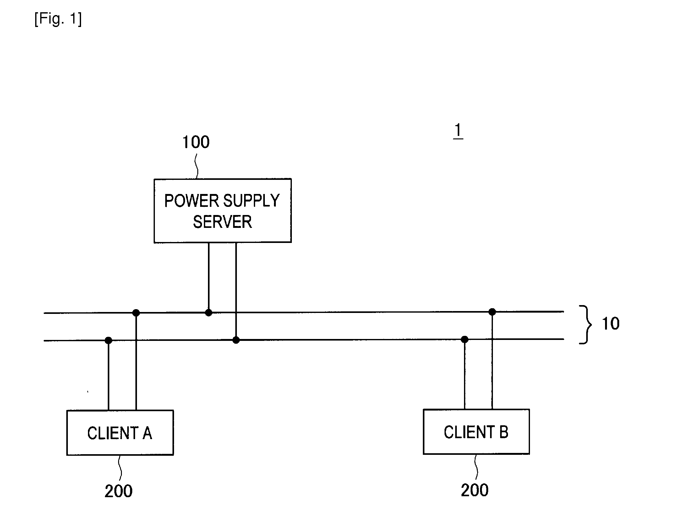
[0026]First, a constitution of a power supply system according to a first embodiment of the present invention will be described. FIG. 1 is an explanatory view showing the constitution of the power supply system according to the first embodiment. Hereinafter, the constitution of the power supply system according to the first embodiment will be described using FIG. 1.

[0027]As shown in FIG. 1, a power supply system 1 is configured to include a power supply server 100 and a client 200. The power supply server 100 and the client 200 are connected to each other through a bus line 10, which, as shown, may include separate conductors.

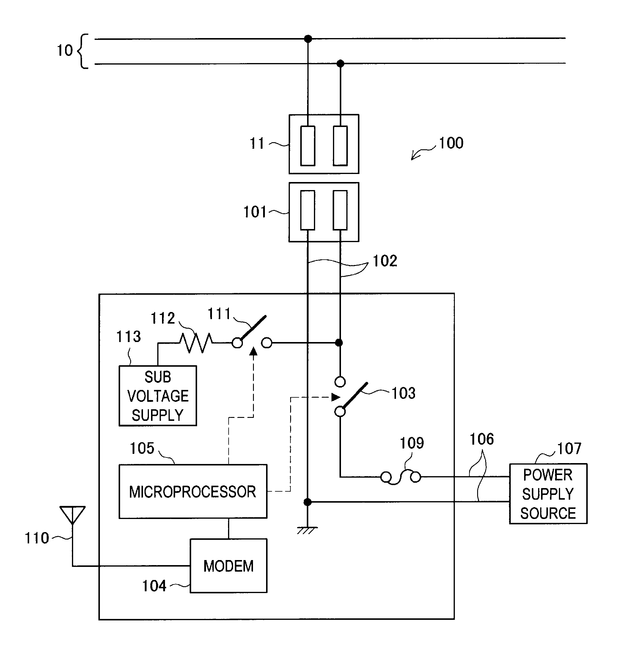
[0028]The power supply server 100 supplies DC power to the client 200. The power supply server 100 further transmits and receives an information signal to and from the client 200. In the present embodiment, the DC power supply and the transmission and reception of the information signal between the powe...

second embodiment

2. Second Embodiment of the Present Invention

[0073]In the above description, there has been described the power supply system in which, although electric power is supplied through a wire, information is transmitted and received wirelessly. Next, there will be described a power supply system in which both the electric power supply and the transmission and reception of information are performed wirelessly. The following description assumes that the ID of the power supply system is set manually, although other automated methods of setting the ID may be used.

[0074]Since a power transfer line is not a bus line but a space (e.g., an air gap or other propagation medium), transferable electric power is not DC but AC. Nevertheless, this space is a type of medium for conveying information and electromagnetic energy. In the present embodiment, the form in which the energy is conveyed is not limited, and so the form of electric energy may be AC, which may be used to excite an antenna and produc...


PUM


Abstract

A power sever, client and method cooperate to selectably supply power from a power server to a client in a format that is acceptable to the client. The client device is able to distinguish the power server from other power servers based on an identification of the power server transmitted to the client device. The client device is then able to specify, or select, from the specific power server the format of the energy to be conveyed to the client device for ultimate consumption by the client device. The conveyance of energy is provided over conductors or wirelessly.

Description

TECHNICAL FIELD[0001]The present invention relates to a power supply device, a power receiving device, and a power supply method.BACKGROUND ART[0002]Many electronic devices such as personal computers and game machines use an AC adaptor, which inputs an alternating-current (AC) power from a commercial power supply and outputs electric power in a format compatible with the device, for the purpose of operating the device and charging the battery. Although the electronic device is usually operated by a direct current (DC), the voltage and current are different in each device. Thus, the AC adaptor outputting electric power matching each device is also different for each device. Thus, even if AC adaptors have similar shapes, they can be incompatible with each other, and there is an issue that the number of AC adaptors increases with increasing numbers of devices.[0003]In order to solve the above issue, there has been proposed a power bus system in which a power supply block supplying elec...

Claims


Application Information

Patent Timeline
Patent Type & Authority Applications(United States)
IPC IPC(8): G06F1/26H04W52/04H02J13/00
CPCG06F1/266G06F1/26H02J50/00
Inventor REKIMOTO, JUNICHITAJIMA, SHIGERU
Owner SONY CORP
Why Eureka
Try Eureka