Syringe cap remover

a technology of syringe cap and remover, which is applied in the field of syringe cap remover, can solve the problems of difficult to achieve exactly the right degree of flexibility in the fingers, and achieve the effect of reducing the failure rate of assembled injection devices, convenient use and reliability

Inactive Publication Date: 2012-07-26
OWEN MUMFORD
View PDF2 Cites 77 Cited by
  • Summary
  • Abstract
  • Description
  • Claims
  • Application Information

AI Technical Summary

Benefits of technology

[0006]It is an object of the present invention to provide a sheath removal mechanism that

Problems solved by technology

Considering the sheath removal solution outlined in the previous paragraphs, it may be difficult to achieve exactly the right degree of flexibility in

Method used


Image

  • Syringe cap remover
  • Syringe cap remover
  • Syringe cap remover

Examples


Embodiment Construction

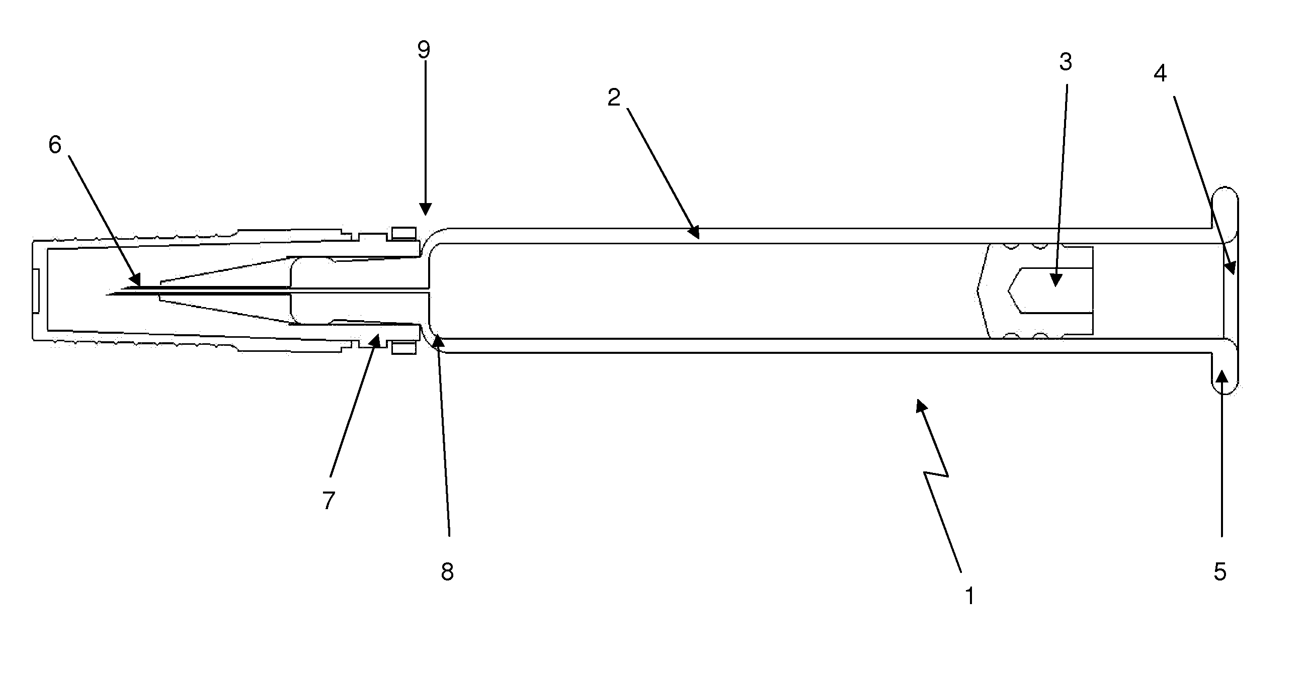
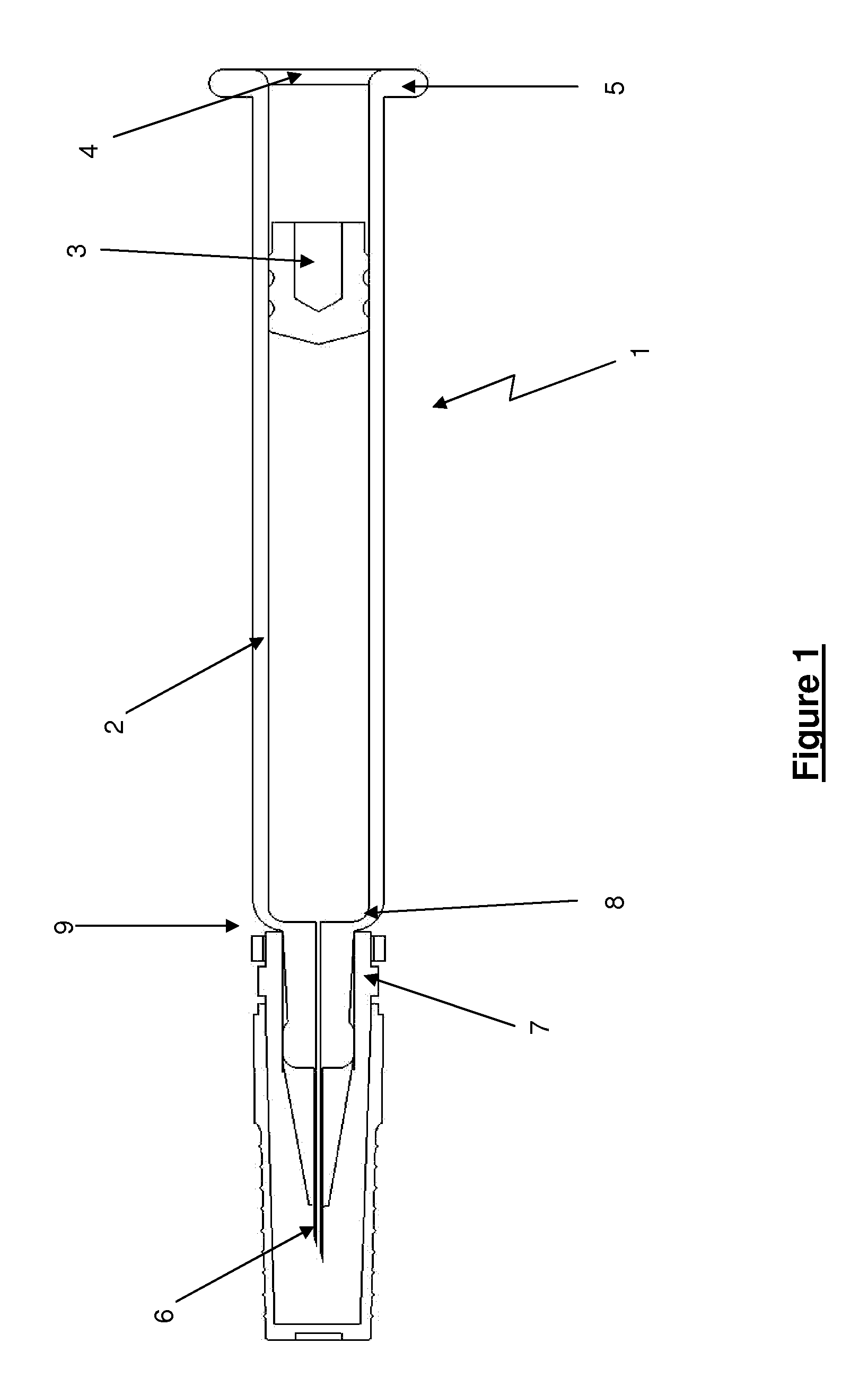
[0031]Apparatus will now be described that enables the easy and reliable removal of a sheath or cap covering a needle of a pre-filled syringe. As has already been outlined above, an assembler of injection devices (e.g. auto-injectors and the like) will typically obtain pre-filled syringes from a supplier. The assembler may have little or no influence over the design of the syringes including the sheaths, and may therefore have to ensure that its device design and assembly process is compatible with the syringe design.

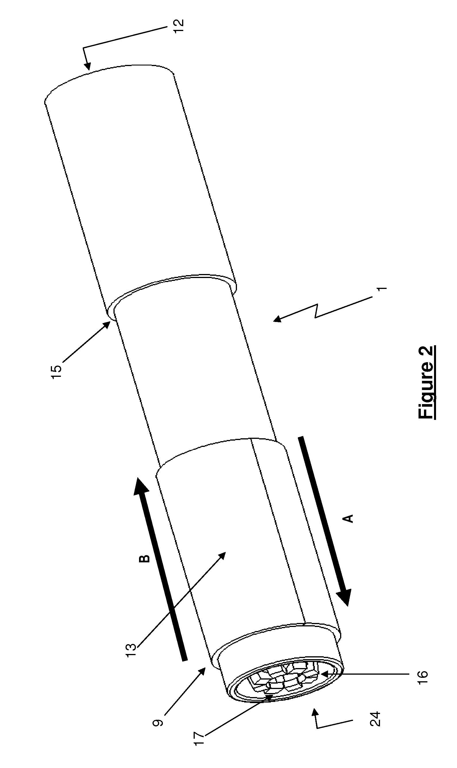
[0032]FIG. 1 shows a conventional syringe 1, comprising a body 2 containing the medicament, a plunger 3 located within the body and which may extend outwardly therefrom, an annular lip 4, wings 5 and a hypodermic needle 6 coupled to the opposite end of the body. An essentially solid rubber or rubber and plastics sheath 7 covers the needle 6 and seals around a shoulder portion of the syringe body 2. An additional sheath cover 33 is shown provided on the outside of the sh...


PUM

PropertyMeasurementUnit
Injection velocityaaaaaaaaaa

Abstract

An apparatus for removing a sheath from a syringe. The sheath provides a sterile cover for a needle of the syringe. The apparatus includes a substantially cylindrical housing defining an opening for receiving a sheath attached to a syringe, and a driver mounted on the housing and being slideable along the housing between first and second axially displaced positions. The apparatus further includes a plurality of radially deflectable fingers mounted within the housing and being coupled to the driver for movement therewith. The fingers are configured such that movement of the driver from the first to the second position causes the fingers to slide over the sheath and engage with a formation on the sheath. Movement of the driver from the second position towards the first position causes the fingers to push the sheath off the syringe. Also provided is an injection device including the apparatus.

Description

TECHNICAL FIELD[0001]The present invention relates to syringe sheath removers and to injection devices incorporating such removers.BACKGROUND[0002]Various types of injection devices are available for assisting with the injection of a medicament into a patient (human or animal), and which are configured to receive a standard, pre-filled glass or plastic syringe tipped with an injection needle. These devices may have a dose setting mechanism and a main drive spring for driving a plunger into the syringe so as to expel the medicament out through the needle. Injection devices may comprise a further spring for driving the needle out of the device housing and into the patient's skin, prior to activation of the main drive spring to expel the medicament.[0003]In order to maintain sterility prior to use, and to avoid “sticking” injuries, the pre-filled syringe is supplied to the injection device assembler with a rubber or rubber and plastic cap, known as a “sheath” or “boot”, covering the ne...

Claims


Application Information

Patent Timeline
IPC IPC(8): B23P19/00
CPCA61M5/2033A61M5/24A61M5/3202Y10T29/53A61M2005/2407A61M2005/2488A61M5/3204
Inventor EDGINTON, ALEX
Owner OWEN MUMFORD
Why Eureka
Try Eureka