Ballistic effect compensating reticle and aim compensation method

a compensation method and ballistic effect technology, applied in the direction of aiming means, weapons, sighting devices, etc., can solve the problems of essentially wrong long range reticles presently employed in the prior art system

Active Publication Date: 2012-07-26
TUBB G DAVID
View PDF2 Cites 54 Cited by
  • Summary
  • Abstract
  • Description
  • Claims
  • Application Information

AI Technical Summary

Benefits of technology

[0050]In addition, the windage offset adjustment indicia on each windage adjustment axis are not symmetrical about the vertical crosshair, meaning that selected windage offset adjustment indicator on the left side of the vertical crosshair is not spaced from the vertical crosshair at the same lateral distance as the corresponding windage offset adjustment indicator on the right side of the vertical crosshair. Instead, the reticle and method of the present invention define differing windage offsets for (a) wind from the left and (b) wind from the right. Those windage offsets refer to an elevation adjustment axis which diverges laterally from the vertical crosshair. The elevation adjustment axis defines the diverging array of elevation offset adjustment indicia for selected ranges (e.g., 300 to 1600 yards, in 100 yard increments). An elevation offset adjustment axis line could be drawn through all of the elevation offset adjustment indicia (corresponding to no wind) to define only the predicted effect of spin drift and precession, as described in this applicant's U.S. Pat. No. 7,325,353.

Problems solved by technology

The variations in the anomalies were observed to be repeatable, and so a precise evaluation of the anomalies was undertaken and it was discovered that all of the long range reticles presently employed in the prior art systems are essentially wrong.

Method used


Image

  • Ballistic effect compensating reticle and aim compensation method
  • Ballistic effect compensating reticle and aim compensation method
  • Ballistic effect compensating reticle and aim compensation method

Examples


Embodiment Construction

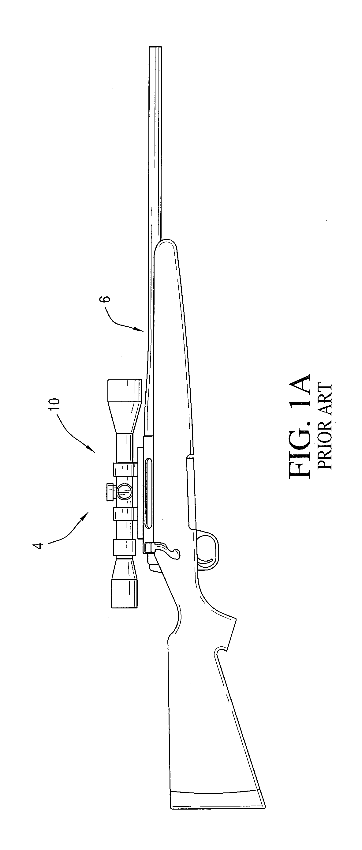
[0071]Referring again to FIGS. 1A-1E. FIG. 1A's projectile weapon system 4 including a rifle 6 and a telescopic rifle sight or projectile weapon aiming system 10 are illustrated in the standard configuration where the rifle's barrel terminates distally in an open lumen or muzzle and rifle scope 10 is mounted upon rifle 6 in a configuration which allows the rifle system 4 to be adjusted such that a user or shooter sees a Point of Aim (“POA”) in substantial alignment with the rifle's Center of Impact (“COI”) when shooting or firing selected ammunition (not shown) at a selected target (not shown).

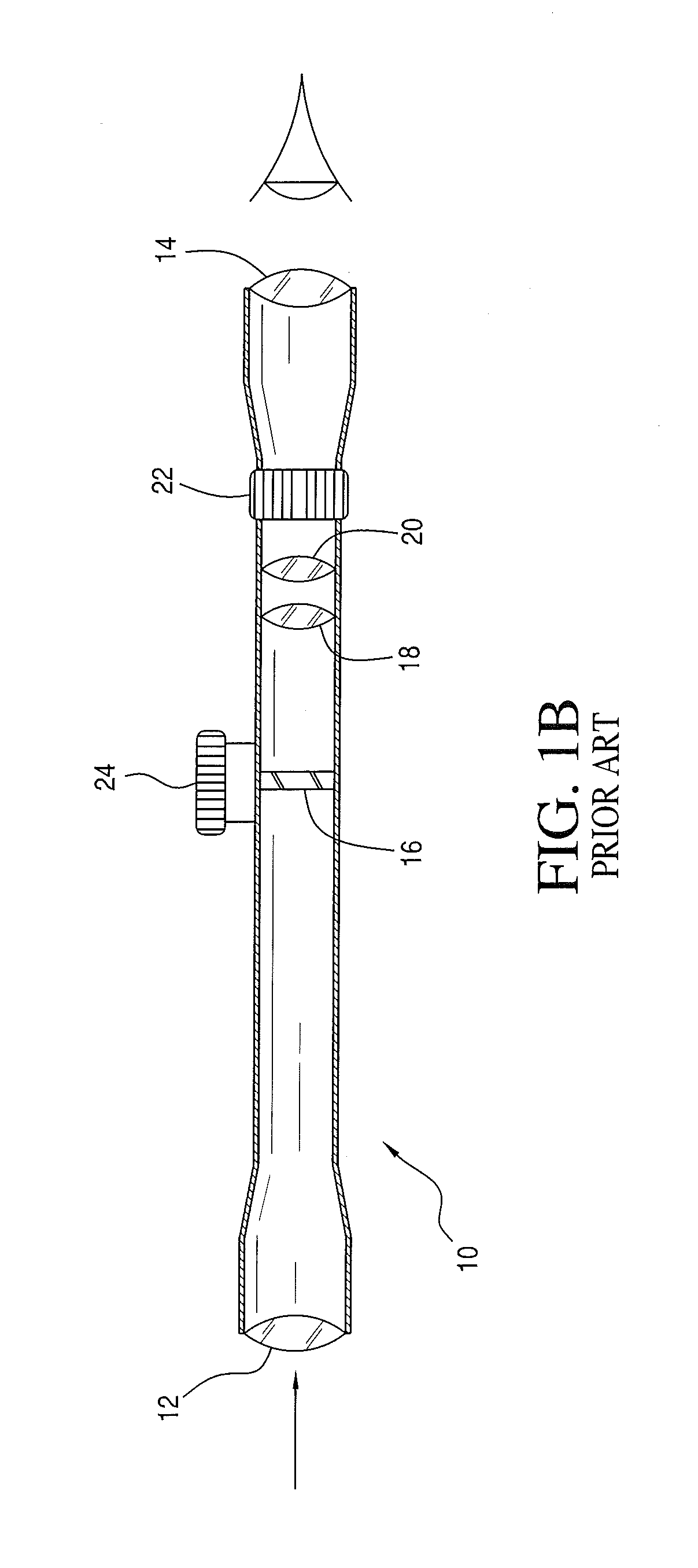
[0072]FIG. 1B schematically illustrates exemplary internal components for telescopic rifle sight or projectile weapon aiming system 10, with which the reticle and system of the present invention may also be used. As noted above, rifle scope 10 generally includes a distal objective lens 12 opposing a proximal ocular or eyepiece lens 14 at the ends of a rigid and substantially tubular body or ho...


PUM


Abstract

A ballistic effect compensating reticle (e.g., 200 or 300) and aim compensation method for rifle sights or projectile weapon aiming systems includes a multiple point elevation and windage aim point field (e.g., 150 or 350) including a primary aiming mark (e.g., 158 or 358) indicating a primary aiming point adapted to be sighted-in at a first selected range and a plurality of secondary aiming points arrayed beneath the primary aiming mark. The method for compensating for a projectile's ballistic behavior while developing a field expedient firing solution permits the shooter to express the field expedient firing solution in units of distance, (e.g., yards or meters, when describing or estimating range and nominal air density ballistic characteristics), and velocity (e.g., mph or kph, for windage hold points).

Description

PRIORITY CLAIMS AND CROSS-REFERENCE TO RELATED APPLICATIONS[0001]This application claims priority to and is related to co-pending:[0002](1) commonly owned U.S. provisional patent application No. 61 / 429,128, filed Jan. 1, 2011, and (2) commonly owned U.S. provisional patent application No. 61 / 437,990, filed Jan. 31, 2011, the entire disclosures of which are incorporated herein by reference.BACKGROUND OF THE INVENTION[0003]1. Field of the Invention[0004]The present invention relates to optical instruments and methods for aiming a rifle, external ballistics and methods for predicting projectile's trajectory. This application relates to projectile weapon aiming systems such as rifle scopes, to reticle configurations for projectile weapon aiming systems, and to associated methods of compensating for a projectile's external ballistic behavior while developing a field expedient firing solution.[0005]2. Discussion of the Prior Art[0006]Rifle marksmanship has been continuously developing ove...

Claims


Application Information

Patent Timeline
Patent Type & Authority Applications(United States)
IPC IPC(8): F41G1/38
CPCF41G1/38F41G3/08F41G1/473
Inventor TUBB, G. DAVID
Owner TUBB G DAVID
Why Eureka
Try Eureka