Automated surgical rod cutter and bender including a power-base, assembly for rod cutting, and assembly for rod bending

a technology of surgical rods and bending rods, which is applied in the direction of forging presses, forging/pressing/hammering devices, forging presses, etc., can solve the problems of large floor or counter space, difficult for operating room personnel to handle, and large weight, and achieve the effect of precise changes in the linearity of rods

Inactive Publication Date: 2012-07-26
LODAHI SEBSTIAN +2
View PDF0 Cites 34 Cited by
  • Summary
  • Abstract
  • Description
  • Claims
  • Application Information

AI Technical Summary

Benefits of technology

[0024]Another advantage of the present invention is the ability to move the lateral dynamic pivots on the bending assembly allowing for more precise changes in linearity of the rod.
is the ability to move the lateral dynamic pivots on the bending assembly allowing for more precise changes in linearity of the rod.

Problems solved by technology

This device is large and heavy, thus occupying much floor or counter space and would be difficult for operating room personnel to handle.
Hydraulic pressurized power sources are not widely available in operating room.
Furthermore, this device is not designed to be sterilized nor be used in the sterile field.
Said devices are often manually actuated, therefore requiring significant force by the operator to affect cutting or bending of the rod.
One operator applies significant muscular force to the levers, increasing risk of injury or failure of operation.
The muscular force required to operate some manual rod cutters and rod benders is great enough to limit the persons able to properly handle the devices.
For the purpose of cutting short segments the operator's hands are dangerously close to the cutting blades and cannot contain the cut rod segments.
The continued requirement for significant muscular force by the user is a disadvantage.
Another disadvantage of this device is the lack of visual confirmation by line of sight to the cutting point immediately prior to and during the operation of cutting due to the rod being enclosed in an opaque housing.
Similar to other prior art the blades are reused and integral to the device but are also prone to dulling or failing over time, therefore requiring periodic sharpening or entire device replacement.
The aforementioned manual devices require two-user operation and considerable muscular force by one user regardless of whether the device is handheld, table-mounted, single-levered or double-levered.
None of the current surgical rod cutter devices accommodates a rod bending assembly.
Given the necessarily rigid rod materials this requires significant force by the user and often requires two-user operation in which one user holds the rod and a second user utilizes both hands to apply force to the levers.
Given the rigidity of the rods available for surgical constructs, these methods require significant muscular forces by the user.
Disadvantages include two-person operation when ex-situ and the need for significant muscular forces by the user.
Several disadvantages are the significant increases in complexity over prior art with respect to operation, sterilization, and cost.
Furthermore this device does not perform rod cutting.
None of the current surgical rod bending devices accommodate a rod cutting assembly.

Method used


Image

  • Automated surgical rod cutter and bender including a power-base, assembly for rod cutting, and assembly for rod bending
  • Automated surgical rod cutter and bender including a power-base, assembly for rod cutting, and assembly for rod bending
  • Automated surgical rod cutter and bender including a power-base, assembly for rod cutting, and assembly for rod bending

Examples


Embodiment Construction

I. Overview

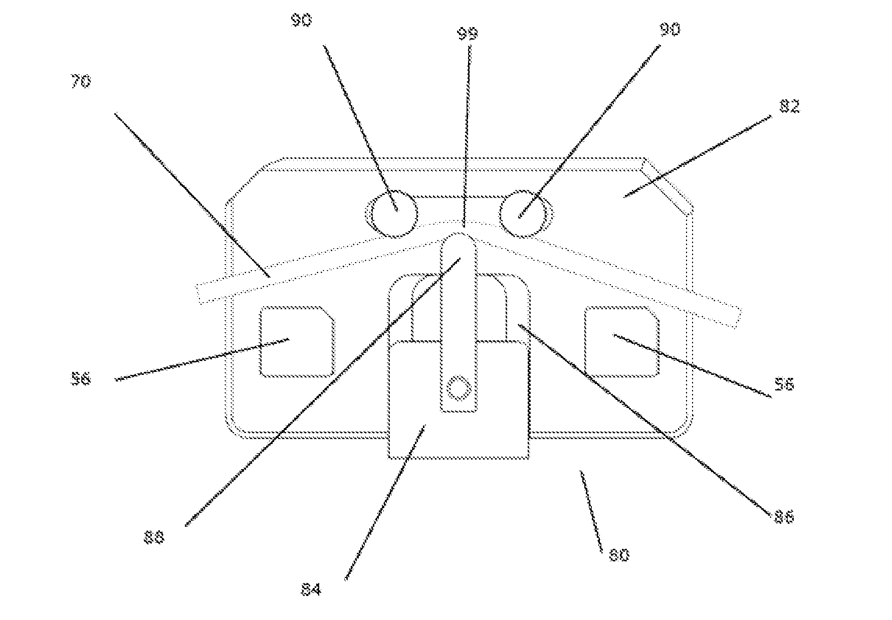
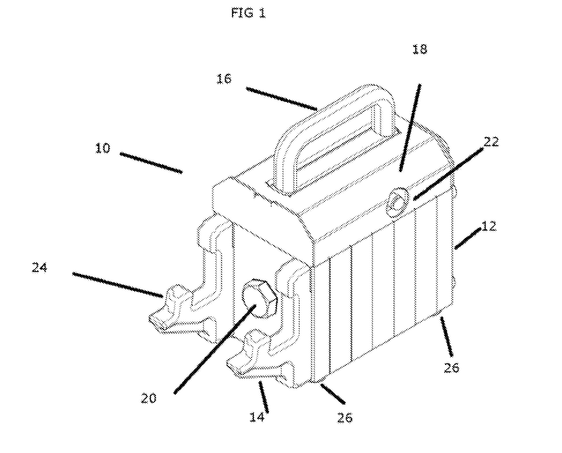
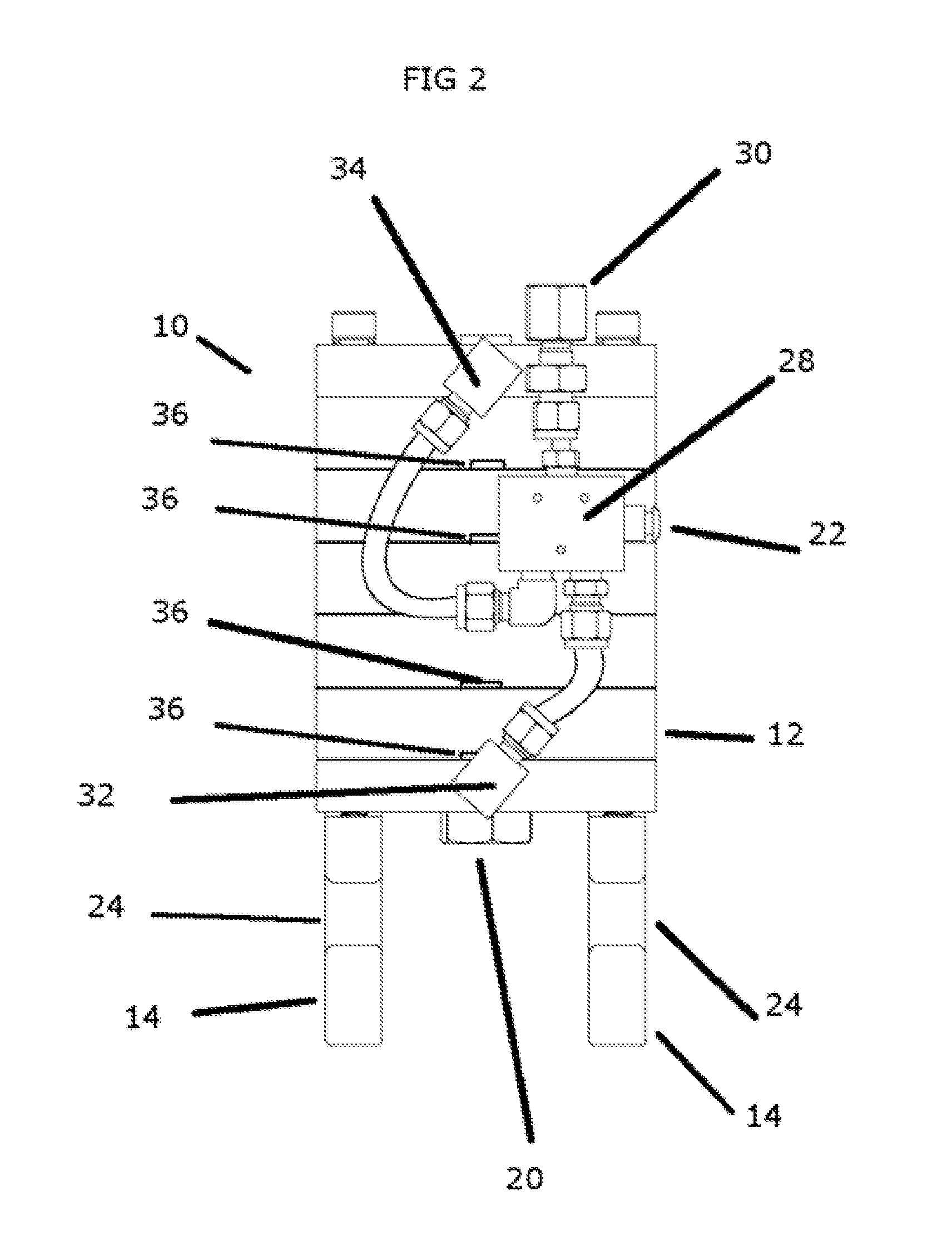
[0033]The automated rod manipulator consists of a power-base 10 as shown in the drawings that is a portable table top tool that is specifically designed and adapted for the manipulation of high strength surgical implant rods used for orthopedic surgery. The rod must be custom fitted to the patient during operation and consequently is required to be cut and bent quickly, cleanly, sterilely, and easily during the operation. Due to the strength of the metals used for surgical implants, large manual shear and wedge cutters and manual rod benders have been traditionally used. These have the disadvantages of being large and unwieldy, imprecise, and requiring significant muscular force and / or body weight to use. The automated rod manipulator consists of a power-base 10 and an array of attachments for manipulating the rod, including the cutting assembly 50 and bending assembly 80.

II. Power-Base

[0034]The power-base 10 is the main power source for manipulating the rod. It is portab...


PUM

PropertyMeasurementUnit
diameteraaaaaaaaaa
diameteraaaaaaaaaa
diametersaaaaaaaaaa

Abstract

A rod manipulator including power-base and various assemblies, interchangeably attaching to the base. The power-base is composed of a pneumatic cylinder and piston which affects the function of various assemblies. The piston moves the central component of an assembly toward the fixed portion of that assembly. A bending assembly containing mobile pivots around which a surgical metal rod can be bent. A cutting assembly containing blades in central and fixed portions between which a surgical metal rod can be cut. The distal end of the cut rod is retained by replaceable, sterilizable, eject-grips during and immediately after the cutting operation. The general object of the invention is to provide an improved surgical rod cutter and surgical rod bender, capable of performing both tasks with one power source, requires one-person operation, eliminates the need for significant muscular forces and eliminates the opportunity for an unsafe projectile in the operating room.

Description

[0001]This document is the nonprovisional patent application for the following provision patent application:[0002]Provisional Patent Application No. 61 / 461,942[0003]Provisional Patent Application Date: Jan. 25, 2011FIELD OF THE INVENTION[0004]This invention relates generally to a surgical rod cutter and surgical rod bender used to reduce the length and / or change the linearity of a surgically implanted metal rod. This specific invention is generally related to a rod cutting tool with one or two blades removably attached to a pneumatic cylinder and a rod bending tool with two positionable pivot points and one central thrust anvil removably attached to a pneumatic cylinder.BACKGROUND OF THE INVENTIONPrior Art[0005]A surgical rod cutter and surgical rod bender reduces the length or changes the linearity of surgical rod. High strength surgical rods are composed of a variety of materials including stainless steel, titanium, and cobalt-chrome alloys. High strength surgical rods are availab...

Claims


Application Information

Patent Timeline
Patent Type & Authority Applications(United States)
IPC IPC(8): A61B17/56B21D7/00B23D23/00
CPCB23D15/02A61B17/8863B23D15/14Y10T83/8759Y10T83/8858Y10T83/7487Y10T83/869
Inventor LODAHI, SEBSTIANLEARD, RYANKARAS, CHRIS
Owner LODAHI SEBSTIAN
Why Eureka
Try Eureka