Sensing system and method

a technology of sensing system and gas, applied in the field of sensing system and method, can solve problems such as false readings

Active Publication Date: 2020-12-10
GENERAL ELECTRIC CO
View PDF0 Cites 0 Cited by
  • Summary
  • Abstract
  • Description
  • Claims
  • Application Information

AI Technical Summary

Benefits of technology

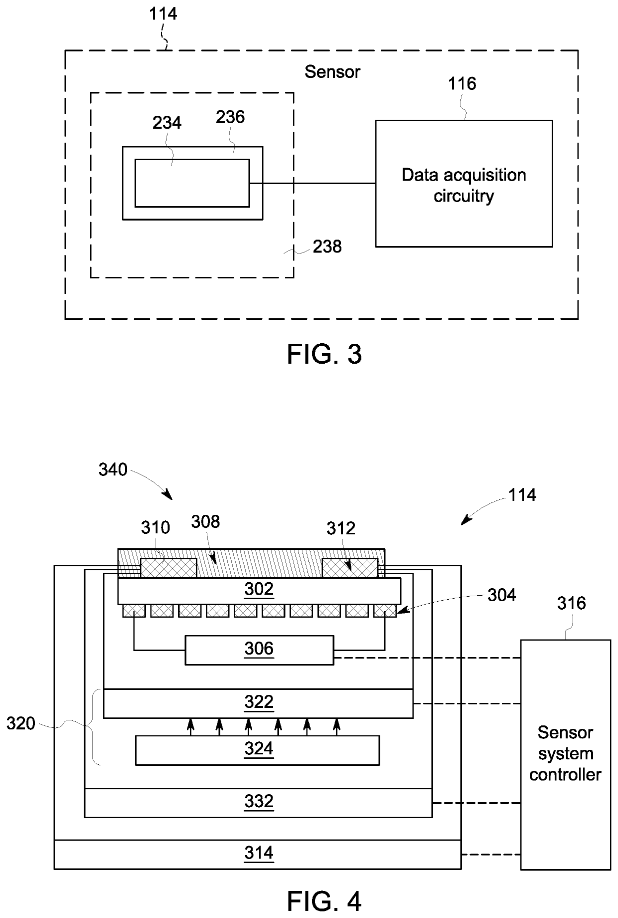
[0004]In one or more embodiments, a sensor system includes a sensing element that includes a sensing material and electrodes configured to apply a first electrical stimuli to the sensing material at an electrical excitation frequency, a modifier assembly including one or more circuits configured to change an electrical impedance of the sensing element, and one or more processors configured to control the modifier assembly. Responsive to exposure of gas to the sensing element, the one or more processors change a linearity of a first electrical signal received from the sensing element by changing the electrical impedance of the sensing element and applying a second electrical stimuli to the sensing material at the electrical excitation frequency.
[0005]In another embodiment, a method includes applying a first electrical stimuli at an electrical excitation frequency to a sensing material of a sensing element via electrodes. A first electrical signal is received from the sensing element that is representative of a resistance of the sensing material during exposure of the sensing material to the first electrical stimuli. A linearity of the first electrical signal received from the sensing element is changed by changing an electrical impedance of the sensing element and applying a second electrical stimuli at the electrical excitation frequency to the sensing material.
[0006]In another embodiment, a method includes applying electrical stimuli at a single electrical excitation frequency to a sensing material of a sensing element via electrodes. A first electrical signal is received from the sensing element that is representative of a resistance response of the sensing material during exposure of the sensing material to the electrical stimuli. A second electrical signal is received from the sensing element that is representative of an impedance response of the sensing material at the single electrical excitation frequency. A linearity of the first electrical signal received from the sensing element changes by changing a configuration of a modifier assembly of the sensing element to change an impedance of the sensing element based on one or more of the impedance response of the sensing material or the resistance response of the sensing material.
[0007]In another embodiment, a method includes applying electrical stimuli at two or more electrical excitation frequencies to a sensing material of a sensing element via electrodes. Electrical signals are received from the sensing element during exposure of the sensing material to the electrical stimuli. A first electrical signal is representative of a resistance response of the sensing material during exposure of the sensing material to the electrical excitation frequencies, and a second electrical signal is representative of an impedance response of the sensing material during exposure of the sensing material to the electrical excitation frequencies. A linearity of one or more of the electrical signals received from the sensing element is changed by changing a configuration of a modifier assembly of the sensing element to change an impedance of the sensing element based on one or more of the resistance response of the sensing material or the impedance response of the sensing material.

Problems solved by technology

Often, sensors demonstrate saturation of their response at high concentrations leading to false readings.

Method used


Image

  • Sensing system and method
  • Sensing system and method
  • Sensing system and method

Examples


Embodiment Construction

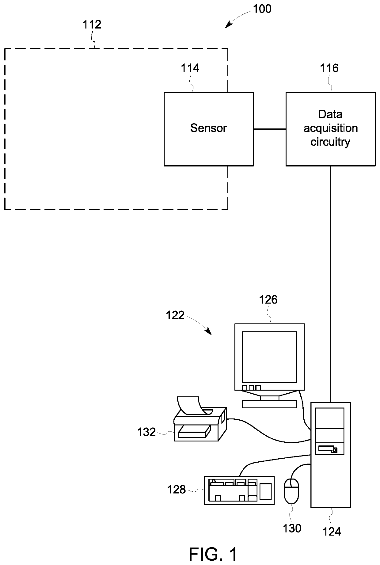
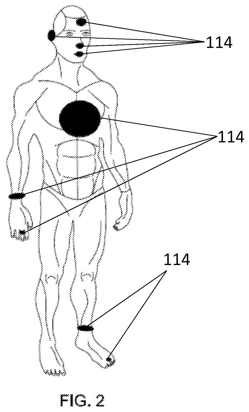
[0023]One or more embodiments of the inventive subject matter described herein provide sensing systems and methods that provide reconfiguration of sensitivity and dynamic range of gas measurements. The systems and methods apply electrical stimuli at a single excitation frequency to a sensing material via sensing electrodes. Responsive to exposure of gas to a sensing element of the sensor, one or more processors change a linearity of a first electrical signal by changing the electrical impedance of the sensing element with a modifier assembly. A second electrical stimuli is applied to the sensing material at the same single excitation frequency. A linearity of the electrical signal is changed by changing the impedance of the sensing element of the sensor.

[0024]In one or more embodiments of the inventive subject matter described herein, the sensing material is a metal oxide, an inorganic material, a composite material, an organic material, a polymeric material, a nanomaterial, or the ...


PUM

PropertyMeasurementUnit
thicknessaaaaaaaaaa
frequencyaaaaaaaaaa
frequencyaaaaaaaaaa

Abstract

A sensor system includes a sensing element that includes a sensing material and electrodes configured to apply a first electrical stimuli to the sensing material at an electrical excitation frequency, a modifier assembly including one or more circuits configured to change an electrical impedance of the sensing element, and one or more processors configured to control the modifier assembly. Responsive to exposure of gas to the sensing element, the one or more processors change a linearity of a first electrical signal received from the sensing element by changing the electrical impedance of the sensing element and applying a second electrical stimuli to the sensing material at the electrical excitation frequency.

Description

FIELD[0001]One or more embodiments are disclosed that relate to systems and methods for sensing gases.BACKGROUND[0002]Gas sensors are based on sensing materials that include metal oxide semiconductors (MOS) materials, dielectric polymers, conducting polymers, nanotubes, metal organic frameworks, graphene, supramolecular compounds, and some others. Often, sensors demonstrate saturation of their response at high concentrations leading to false readings.[0003]Conventional sensors have relatively narrow dynamic range of measurements due to the nature of the interaction mechanisms of sensing materials with the ambient environment. For example, while MOS materials have the biggest commercial success because of their broad applications for gas alarms in residential and industrial facilities, the readout of MOS materials is conventionally performed by measuring resistance change of the material as a function of gas concentration. Such relation follows a well-known power law with a saturatio...

Claims


Application Information

Patent Timeline
Patent Type & Authority Applications(United States)
IPC IPC(8): G01N27/12
CPCG01N27/122G01N27/12G01N27/123G01N27/124
Inventor POTYRAILO, RADISLAV ALEXANDROVICHST. PIERRE, RICHARDAMM, BRUCE COURTNEY
Owner GENERAL ELECTRIC CO
Why Eureka
Try Eureka