Method for cutting a workpiece using a laser beam

A workpiece, laser technology, used in laser welding equipment, manufacturing tools, metal processing equipment, etc., can solve problems such as damage to cutting contours

Active Publication Date: 2019-06-07
TRUMPF WERKZEUGMASCHINEN GMBH & CO KG
View PDF14 Cites 0 Cited by
  • Summary
  • Abstract
  • Description
  • Claims
  • Application Information

AI Technical Summary

Problems solved by technology

Furthermore, when piercing directly on the cutting contour, the cutting contour is damaged

Method used


Image

  • Method for cutting a workpiece using a laser beam
  • Method for cutting a workpiece using a laser beam
  • Method for cutting a workpiece using a laser beam

Examples


Embodiment Construction

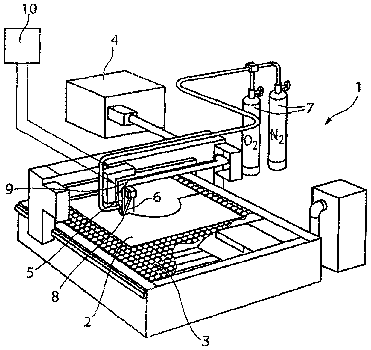
[0033] figure 1 A laser cutting machine 1 is shown for laser cutting a workpiece 2 which is arranged on a workpiece support 3 . The laser cutting machine 1 has a laser beam generator 4 which is designed as a diode laser in the exemplary embodiment. In an alternative embodiment it is provided that the laser beam generator 4 is designed as a CO 2 lasers or solid-state lasers. Additionally, from figure 1 The cutting head 5 can be seen in . A laser beam 6 is generated in the laser beam generator 4 , which is guided from the laser beam generator 4 to the cutting head 5 by means of a light guide or deflection mirror. Laser beam 6 is directed onto workpiece 2 by means of focusing optics arranged in cutting head 5 .

[0034]Furthermore, the laser cutting machine 1 is supplied with cutting gases 7 , in this embodiment oxygen and nitrogen. The cutting gas 7 enters a nozzle (cutting gas nozzle) 8 of the cutting head 5 from which it emerges together with the laser beam 6 . Furtherm...


PUM


Abstract

The invention relates to a method for cutting a preferably planar and/or metal workpiece (2, 2') along a predefinable cutting contour (100, 100') using a laser beam (6) and a cutting gas (7) emitted from a nozzle (8), wherein the laser beam (6) makes a recess in the workpiece (2, 2') so as to form a recess hole (101, 101') on the cutting contour (100, 100') or at least partly close to the cuttingcontour (100, 100'). The invention is characterised in that at least two machining parameters are continuously modified during formation of the recess hole (101, 101'), and/or at least one machining parameter is continuously modified on a switch path (107') between the recess hole (101, 101') and an endpoint (108') lying on the cutting contour (100, 100').

Description

technical field [0001] The invention relates to a method for cutting a preferably plate-shaped and / or metallic workpiece along a predeterminable cutting contour by means of a laser beam and cutting gas emerging from a nozzle, wherein the laser beam penetrates into A piercing hole in a workpiece formed on the cutting contour or at least partially beside the cutting contour. Background technique [0002] In the prior art, in the hitherto usual laser cutting of plate-like workpieces, a start-up section before the actual cutting contour is required after the laser beam has penetrated into the workpiece. The activation section is required because a material buildup forms around the piercing hole during piercing. Furthermore, when piercing directly on the cutting contour, the cutting contour is damaged. Furthermore, the respective required cutting parameters must be set at the latest at the start of the actual cutting along the cutting contour. Cutting parameters are, for examp...

Claims


Application Information

Patent Timeline
Patent Type & Authority Applications(China)
IPC IPC(8): B23K26/38B23K26/04
CPCB23K26/048B23K26/38B23K26/1464
Inventor P·马赫M·克鲁茨克W·瓦登Y·布尔德C·克劳斯J·韦贝尔
Owner TRUMPF WERKZEUGMASCHINEN GMBH & CO KG
Why Eureka
Try Eureka